1-1-32 Kamiminami, Hirano-ku, Osaka 547-0003, Japan
A-6573H-1EX Printed in Japan
© 2007 Icom Inc.
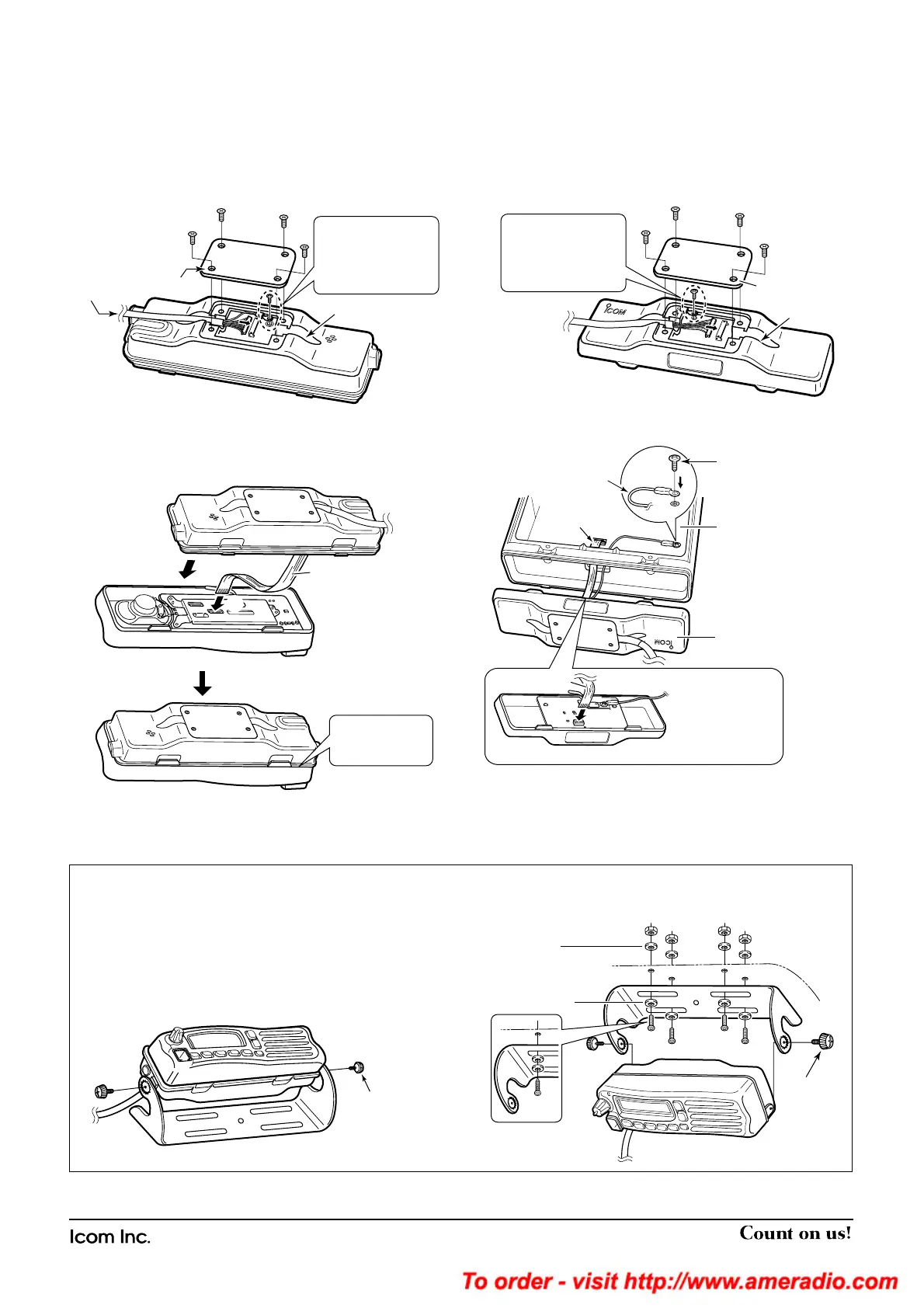
■ Mounting
2 types of mounting styles are available— one is overhead
mounting, and other one is on-board mounting.
Mount the front panel and the attachment securely with the
4 supplied screws to a thick surface which can support more
than 1.5 kg. (Overhead mounting)
On-board mounting
Overhead mounting
■ Attachment
For the front panel attachment:
q Connect the optional OPC-607, OPC-608 or OPC-609 to
the front panel attachment as shown below.
After the cable connection, replace the removed rear plate
and the 4 screws.
• The optional cable can be inserted into either the left or right
grooves as desired on the back of the attachment.
w Connect the flat cable (q) as shown below, and then at-
tach the front panel and the attachment (w).
• Ensure the flat cable is inserted correctly, and not upside down.
For the main body attachment:
e Connect the optional OPC-607, OPC-608 or OPC-609 to
the main body attachment as shown below.
After the cable connection, replace the removed rear
plate.
• The optional cable can be inserted into either the left or right
grooves as desired on the back of the attachment.
r Connect the supplied flat cable* and ground cable
(coming
from the RMK-3)
as shown below.
*Ensure the flat cable and attachment are inserted/attached cor-
rectly, and not upside down.
t Replace the removed bottom cover and 4 screws, then re-
connect the DC power cable.
 Loading...