SERVICE AND TECHNICAL SUPPORT MANUAL Gas Furnace: (F/G)9MVE
Specifications subject to change without notice.
440 04 4801 00 7
Adjust Manifold Pressure
1. Adjust manifold pressure to obtain low fire input rate.
(See Figure 3)
a. Turn gas valve ON/OFF switch to OFF.
b. Remove manifold pressure tap plug from gas valve.
c. Connect a water column manometer or similar device
to manifold pressure tap.
d. Turn gas valve ON/OFF switch to ON.
e. Move setup SW1—2 on furnace control to ON
position to lock furnace in low−heat operation. (See
Figure 4 and Figure 5)
f. Manually close blower door switch.
g. Jumper R and W/W1 thermostat connections on
control to start furnace. (See Figure 4)
h. Remove regulator adjustment cap from low heat gas
valve pressure regulator (See Figure 3) and turn
low−heat adjusting screw (3/16 or smaller flat−tipped
screwdriver) counterclockwise (out) to decrease input
rate or clockwise (in) to increase input rate.
NOTICE
DO NOT set low−heat manifold pressure less than 1.3−in. w.c.
(324 Pa) or more than 1.7−in. w.c. (423 Pa) for natural gas. If
manifold pressure is outside this range, change main burner
orifices.
i. Install low−heat regulator adjustment cap.
j. Re−install manifold pressure tap plug from gas valve.
k. Move setup switch SW1−2 to OFF position after
completing low−heat adjustment.
l. Leave manometer or similar device connected and
proceed to Step 2.
2. Adjust manifold pressure to obtain high fire input rate.
(See Figure 3)
a. Jumper R to W/W1 and W2 thermostat connections
on furnace control. This keeps furnace locked in
high−heat operation.
b. Remove regulator adjustment cap from high−heat
gas valve pressure regulator (See Figure 3) and turn
high heat adjusting screw (3/16−in. or smaller
flat−tipped screwdriver) counterclockwise (out) to
decrease input rate or clockwise (in) to increase input
rate.
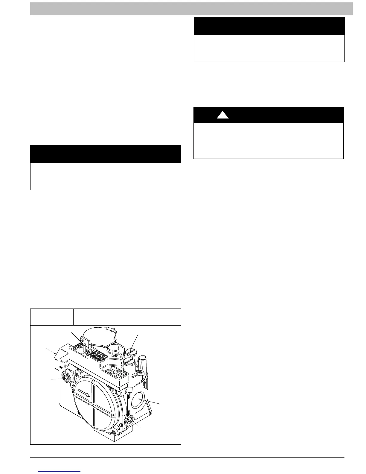
Figure 3
Redundant Automatic Gas Control
Valve (2−Stage)
ON/OFF Switch
Regulator Seal Cap
Regulator Adjustment
Regulator Seal Cap under Cap
1/2” NPT Outlet
1/8” NPT Manifold
Pressure Tap
1/8” NPT Inlet
Pressure Tap
1/2” NPT Inlet
A11152
NOTICE
DO NOT set high−heat manifold pressure less than 3.2−in. w.c.
(797 Pa) or more than 3.8 in. w.c. (947 Pa) for natural gas. If
required manifold pressure is outside this range, change main
burner orifices to obtain manifold pressure in this range.
c. When correct input is obtained, replace caps that
conceal gas valve regulator adjustment screws. Main
burner flame should be clear blue, almost
transparent. (See Figure 14)
d. Re−install manifold pressure tap plug to gas valve.
e. Remove jumpers R to W/W1 and R to W2.
FIRE HAZARD
Failure to follow this warning could result in personal injury,
death, and/or property damage.
Re−install manifold pressure tap plug in gas valve to
prevent gas leak.
!
WARNING
3. Verify natural gas input rate by clocking meter.
NOTE: Contact your HVAC distributor or gas supplier for metric
gas meter Tables, if required.
a. Turn off all other gas appliances and pilots served by
the meter.
b. Move setup switch SW1−2 to ON position. This
keeps furnace locked in low−heat operation when
only W/W1 is energized.
c. Jumper R to W/W1.
d. Run furnace for 3 minutes in low−heat operation.
e. Measure time (in sec) for gas meter to complete 1
revolution and note reading. The 2 or 5 cubic feet dial
provides a more accurate measurement of gas flow.
f. Refer to Table 2 for cubic ft. of gas per hr.
g. Multiply gas rate cu ft./hr by heating value (Btuh/cu
ft.) to obtain input.
h. If clocked rate does not match required input from
Step 1, increase manifold pressure to increase input
or decrease manifold pressure to decrease input.
Repeat steps b through e until correct low−heat input
is achieved. Re−install low heat regulator seal cap on
gas valve.
i. Jumper R to W/W1, and W2. This keeps furnace
locked in high−heat operation when both W/W1 and
W2 are energized.
j. Repeat items (d) through (h) for high−heat operation,
repeating Step 2 and adjusting the high−heat regular
screw, as required.
4. Restore furnace to normal operating condition.
a. Turn gas valve On/Off switch to OFF.
b. Remove water column manometer or similar device
from manifold pressure tap.
c. Replace manifold pressure tap plug to gas valve.
d. Turn gas valve On/Off switch to ON.
e. Move setup SW1−2 on furnace control to position
required for attached thermostat (OFF for
single−stage thermostats, ON for two−stage
thermostats).
f. Check for gas leaks and verify furnace operation.
 Loading...