_i_i{{_;iii]i_i{!_iii1_i_ii}{{{{i_;i_;7_i_i_Hi{7_i_{{{iij;{{_iii_!iii;t_i!iii_ii_i{i_}!_jiii1_{ii_i¸
......L iii"°r'z°nt°l,o vont
Alternate Orientation
l-
-i-
x
ILl
Field
Supplied Tee._\
i'
/
/'
/
/
TeeTrapWhitePVCj
(loosepartsbag)
Ii
Z
OnSome / -
ModelsONLY
Single Pressure Switch Detail
...... _,_
-. _'_._'_._d_ i i
Level or Sloped towards Tee
Dual Pressure Switch
ReliefTubeBlack Rub-
\
\
/ \
_R ji
]
/
/ /
/
FlexibleTubeConnector3/16"
(4.8mm)OD(LoosePartsBag/)/X
/
ReliefTubingExtension/
BlackRubber3/16" (4,8mm)ID
Cutto Fit(LoosePartsBag)
C
Yelloworblack
Plastic Cap
i
,/
/
& Clamps
F _
TrapConnection
Im)
Preassemble&
insertinto furnace
...... ElbowTubeBlackRubber1/2"(12,7r
ID&Clamps(LoosePartsBag)
...... BarbedCouplingt/2"(12,7mm)OD
(LoosePartsBag)
DrainTubeBlackRubber
t/2"(12,7mm)ID&Clamps
\.
\
\ ..... DrainTubeCorrugated/8 (15.9mm)
ID&Clamps
Cutatlstraightsection
Leaveroomforclamp _CutHere
Representativedrawingonly,somemodelsmayvaryinappearance.
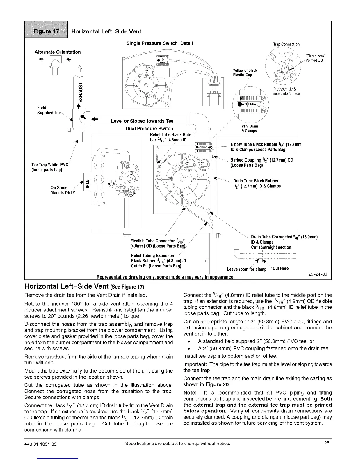
Horizontal Left-Side Vent (SeeFigure17)
Remove the drain tee from the Vent Drain if installed.
Rotate the inducer 180 ° for a side vent after loosening the 4
inducer attachment screws. Reinstall and retighten the inducer
screws to 20" pounds (2.26 newton meter) torque.
Disconnect the hoses from the trap assembly, and remove trap
and trap mounting bracket from the blower compartment. Using
cover plate and gasket provided in the loose parts bag, cover the
hole from the burner compartment to the blower compartment and
secure with screws.
25-24-88
Connect the 3/16" (4.8mm) ID relief tube to the middle port on the
trap. If an extension is required, use the 3/16" (4.8mm) OD flexible
tubing connector and the black 3/16" (4.8mm) ID relief tube in the
loose parts bag. Cut tube to length.
Cut an appropriate length of 2" (50.8mm) PVC pipe, fittings and
extension pipe long enough to exit the cabinet and connect the
vent drain to either:
• A standard field supplied 2" (50.8mm) PVC tee, or
• A 2" (50.8mm) PVC coupling fastened onto the drain tee.
Install tee trap into bottom section of tee.
Important: The pipe to the tee trap must be level or sloping towards
the tee trap
Connect the tee trap and the main drain line exiting the casing as
shown in Figure 20.
Note: It is recommended that all PVC piping and fitting
connections be fit up and inspected before final cementing. Both
the external trap and the external tee trap must be primed
before operation, Verify all condensate drain connections are
securely clamped. A coupling and clamps (in loose part bag) may
be installed as shown for future servicing of the vent system.
Remove knockout from the side of the furnace casing where drain
tube will exit.
Mount the trap externally to the bottom side of the unit using the
two screws provided in the location shown.
Cut the corrugated tube as shown in the illustration above.
Connect the corrugated hose from the transition to the trap.
Secure connections with clamps.
Connect the black 1/2" (12.7mm) ID drain tube from the Vent Drain
to the trap. If an extension is required, use the black 1/2" (12.7mm)
OD flexible tubing connector and the black 1/2" (12.7mm) ID drain
tube in the loose parts bag. Cut tube to length. Secure
connections with clamps.
440 01 1051 03 Specifications are subject to change without notice. 25
 Loading...