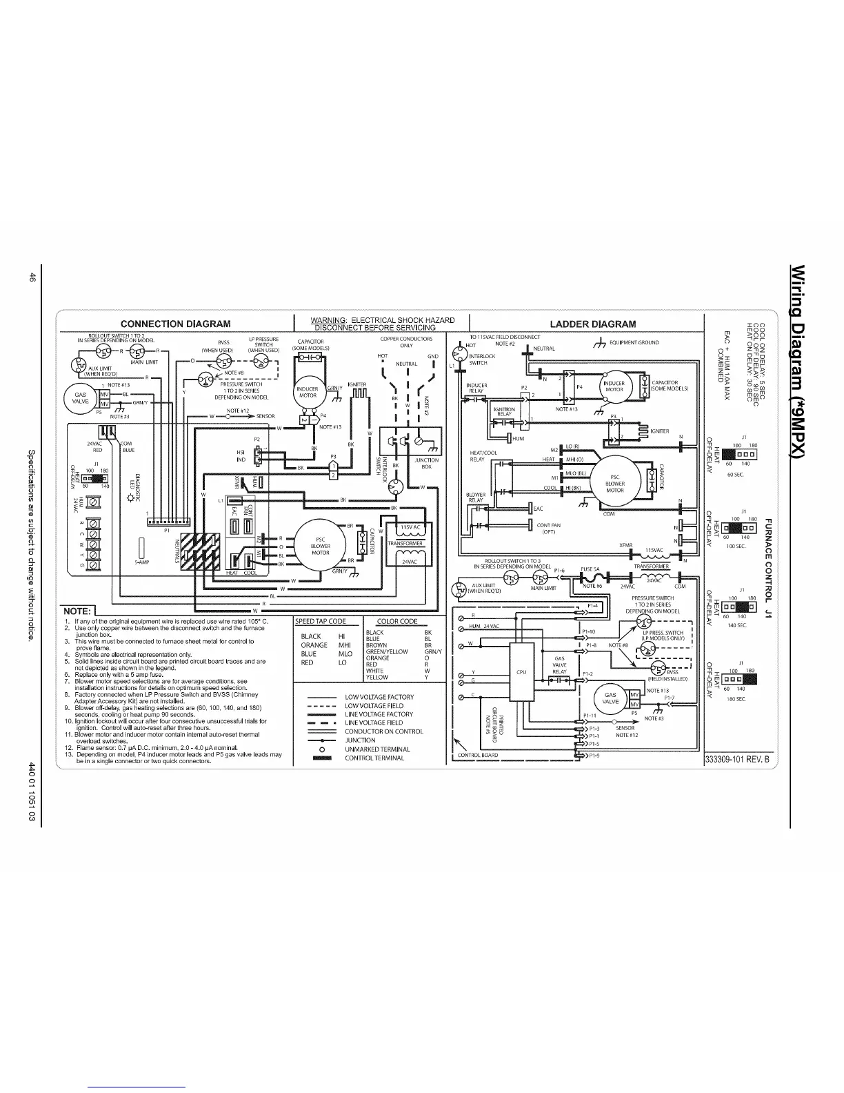
CONNECTION DIAGRAM 1 WARNING:ELECTRICAL SHOCK HAZARD l LADDER DIAGRAM zoo
DISCONNECT BEFORE SERVICING m o o
_>oo
:::,L. ±
R m 0 + Z_Iz
( O o-nu /
GND _. i m C] m /
_0 m m c0c_ F-mr-
DEPENDINGONMODEL \ MOIOR J _ rlUUI BK | --z mOO
GRNHI NOTE,,2
--_F------W_SENSORE3:_P4 / _ M"
mml 100 180 60SEC
-H 60 140
100SEC. _l_
HEAT COOL
- :': _,
fanyoftheo _
Jse only cop_ 140SEC
Thisjunctionprovewireflame,box.mu: ORANGEREDBLUEBLACK_ MLO _MHILOHI,...,..,..j._LOW_1_1E_uA_KWHITEGREENG!_GREEN!YREDBROWN YW0RGRN/YBRBK _"__ 1ooJl 180
-- LOW VOLT/ 80
.... LOW VOLTP
LINE VOLTA
_ LINEVOLT,_
CONDUCT( _D
JUNCTION
0
[ CONTROLBOA
ROLLOUT SWITCH 1 TO 2 TO 115VAC FIELD DISCONNECT
IN SERIES DEPENDING ON MODEL COPPER CONDUCTORS
ROLLOUT SWITCH ] TO 3
TRANSFORMER
_W
I P1-10 LPPRESSSWITCH
333309-10I REV. B
1. If any of the original equipment wire is replaced use wire rated 1050 C. SPEED TAP CODE
2. Use only copper wire between the disconnect switch and the furnace BK
3. This wire must be connected to furnace sheet metal for control to
4. Symbols are electrical representation only. GREEN!YELLOW
5. Solid lines inside circuit board are printed circuit board traces and are
not depicted as shown in the legend.
6. Replace only with a 5 amp fuse.
7. Blower motor speed selections are for average conditions, see
installation instructions for details on optimum speed selection.
8. Factory connected when LP Pressure Switch and BVSS (Chimney LOW VOLTAGE FACTORY
Adapter Accessory Kit) are not installed.
..... LOW VOLTAGE FIELD
9. Blower off-delay, gas heating selections are (60, 100, 140, and 160)
seconds, cooling or heat pump 90 seconds. _ LINEVOLTAGE FACTORY
lO. Ignition lockeut will occur after four consecutive unsuccessful trials for _ _ . LINEVOLTAGEFELD
ignition. Control will auto-reset after three hours.
11. Blower motor and inducer motor contain internal auto-reset thermal CONDUCTOR ON CONTROL
overload switches.
12. Flame sensor: 0.7 pA D.C. minimum, 2.0 -4.0 pA nominal. UNMARKEDTERMINAL
13. Depending on model, P4 inducer motor leads and P5 gas valve leads may CONTROLTERMINAL
be in a single connector or two quick connectors.
Q
x
 Loading...