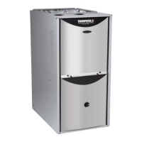
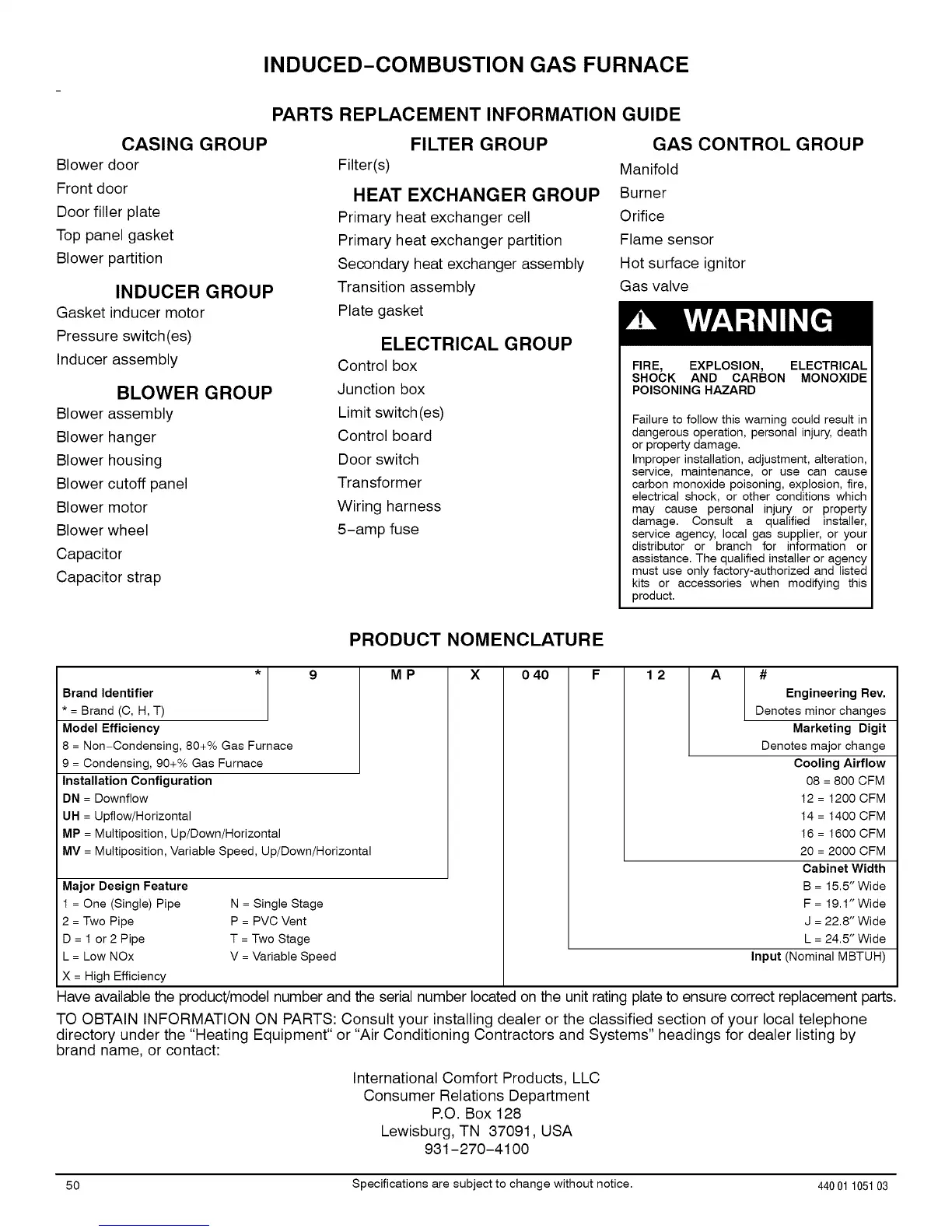
INDUCED-COMBUSTION GAS FURNACE
PARTS REPLACEMENT INFORMATION GUIDE
CASING GROUP
Blower door
Front door
Door filler plate
Top panel gasket
Blower partition
INDUCER GROUP
Gasket inducer motor
Pressure switch(es)
Inducer assembly
BLOWER GROUP
Blower assembly
Blower hanger
Blower housing
Blower cutoff panel
Blower motor
Blower wheel
Capacitor
Capacitor strap
FILTER GROUP
Filter(s)
HEAT EXCHANGER GROUP
Primary heat exchanger cell
Primary heat exchanger partition
Secondary heat exchanger assembly
Transition assembly
Plate gasket
ELECTRICAL GROUP
Control box
Junction box
Limit switch (es)
Control board
Door switch
Transformer
Wiring harness
5-amp fuse
GAS CONTROL GROUP
Manifold
Burner
Orifice
Flame sensor
Hot surface ignitor
Gas valve
FIRE, EXPLOSION, ELECTRICAL
SHOCK AND CARBON MONOXIDE
POISONING HAZARD
Failure to follow this warning could result in
dangerous operation, personal injury, death
or property damage.
Improper installation, adjustment, alteration,
service, maintenance, or use can cause
carbon monoxide poisoning, explosion, fire,
electrical shock, or other conditions which
may cause personal injury or property
damage. Consult a qualified installer,
service agency, local gas supplier, or your
distributor or branch for information or
assistance. The qualified installer or agency
must use only factory-authorized and listed
kits or accessories when modifying this
product.
PRODUCT NOMENCLATURE
* 9
Brand Identifier
* = Brand (C, H, T)
Model Efficiency
8 = Non-Condensing, 80+% Gas Furnace
9 = Condensing, 90+% Gas Furnace
Installation Configuration
DN = Downflow
UH = Upflow/Horizontal
MP = Multiposition, Up/Down/Horizontal
MV = Multiposition, Variable Speed, Up/Down/Horizontal
Major Design Feature
1 = One (Single) Pipe
2 = Two Pipe
D=lor2Pipe
L = Low NOx
X = High Efficiency
N = Single Stage
P = PVC Vent
T = Two Stage
V = Variable Speed
MP X o 40 12 A #
Engineering Rev.
Denotes minor changes
Marketing Digit
Denotes major change
Cooling Airflow
08 = 800 CFM
12 = 1200 CFM
14 = 1400 CFM
16=1600CFM
20 = 2000 CFM
Cabinet Width
B = 15.5"Wide
F = 19.1"Wide
J = 22.8" Wide
L = 24.5" Wide
Input (Nominal MBTUH)
Have available the product!model number and the serial number located on the unit rating plate to ensure correct replacement parts.
TO OBTAIN INFORMATION ON PARTS: Consult your installing dealer or the classified section of your local telephone
directory under the "Heating Equipment" or "Air Conditioning Contractors and Systems" headings for dealer listing by
brand name, or contact:
International Comfort Products, LLC
Consumer Relations Department
P.O. Box 128
Lewisburg, TN 37091, USA
931-270-4100
50 Specifications are subject to change without notice. 440 01105103
 Loading...