Installation
CARBON MONOXIDE POISONING HAZARD
Failure to properly vent this furnace or other
appliances could result in personal injury or death.
This furnace can NOT be common vented or
connected to any type B, BW or L vent or vent
connector, nor to any portion of a factory-built or
masonry chimney. If this furnace is replacing a
previously common-vented furnace, it may be
necessary to resize the existing vent and chimney
to prevent oversizing problems for the other
remaining appliance(s). See Venting and
Combustion Air Check in the Combustion &
Ventilation Air section. This furnace MUST be
vented to the outside.
InstallationPositions
This furnace can be installedin an upflow,horizontal (eitherleft or
right) or downflowairflow position. DO NOT installthis furnace on
its back. For the upflow position, the return air ductwork can be
attachedto eithertheleft or rightside paneland/orthe bottom.For
horizontal and downflowpositions,the return air ductworkmust be
attached to the bottom. The return air ductwork must never be
attachedto the back of thefurnace.
Locationand Clearances
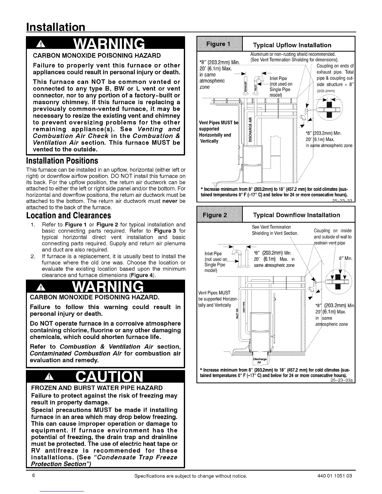
1. Refer to Figure 1 or Figure 2 for typical installation and
basic connecting parts required. Refer to Figure 3 for
typical horizontal direct vent installation and basic
connecting parts required. Supply and return air plenums
and duct are also required.
2. If furnace is a replacement, it is usually best to install the
furnace where the old one was. Choose the location or
evaluate the existing location based upon the minimum
clearance and furnace dimensions (Figure 4).
CARBON MONOXIDE POISONING HAZARD.
Failure to follow this warning could result in
personal injury or death.
Do NOT operate furnace in a corrosive atmosphere
containing chlorine, fluorine or any other damaging
chemicals, which could shorten furnace life.
Refer to Combustion & Ventilation Air section,
Contaminated Combustion Air for combustion air
evaluation and remedy.
FROZEN AND BURST WATER PIPE HAZARD
Failure to protect against the risk of freezing may
result in property damage.
Special precautions MUST be made if installing
furnace in an area which may drop below freezing.
This can cause improper operation or damage to
equipment. If furnace environment has the
potential of freezing, the drain trap and drainline
must be protected. The use of electric heat tape or
RV antifreeze is recommended for these
installations. (See "Condensate Trap Freeze
Protection Section"_
Typical Upflow Installation
Aluminumornon-rustingshieldrecommended.
• .... _H:_ (SeeVentTerminationShieldingfor dimensions)
8 (203 2...) iv,.
.... ,, ; _, ,, _ :__ Couplingon endsof
zU (b / m) tvlax '
in same ' _1 I_ _' exhaust pipe. Total
_ InletPipe pipe &couplingout-
atmospheric _ (notusedon /' side structure = 8"
zone _Ii SinglePipe / (203.2mm)
"_ : - model)
Vent PipesMUST
supported
Horizontallyand
Vertically
Max.
zone
* Increaseminimumfrom8" (203.2mm)to 18" (457.2mm)forcoldclimates(sus-
tainedtemperatures0° F (-17°C)and belowfor 24 ormoreconsecutivehours),
25-2,!-,!3
Typical Downflow Installation
See VentTermination
Shieldingin VentSection.
\
\
\
_1 I_ '\_
InletPipe _ _ *8" (203.2mm) Min.
(notusedon_ _ 20' (6.1m) Max.in
Single Pipe _J_ sameatmosphericzone
model)
VentPipesMUST
besupportedHorizon-
tally andVertically _.
Coupling on inside
andoutsideofwallto
restrainyen!pipe
\ 8" Min.
(203.2mm) air
(6.1m)Max.
same
osphericzone
/
* Increaseminimumfrom8" (203.2mm)to 18" (457.2mm)for coldclimates(sus-
tainedtemperatures0° F (-17°C)andbelowfor 24 ormoreconsecutivehours),
25-23-33a
6 Specifications are subject to change without notice. 440 01 1051 03
 Loading...