C. ROUTINGAND SUSPENDINGREFRIGERANT
LINES
Run refrigerant lines as straight and direct as possible,
avoiding unnecessary bends and turns. Always insulate
the entire suction line. Both lines should be insulated
when routed through an attic or when routed through an
underground raceway.
When routing refrigerant lines through a foundation or
wall, do not allow refrigerant lines to come in direct
contact with the building structure. Make openings large
enough so that lines can be wrapped with extra insulation.
Fill all gaps with RTV caulk. This will prevent noise
transmission between the tubing and the foundation or
wall.
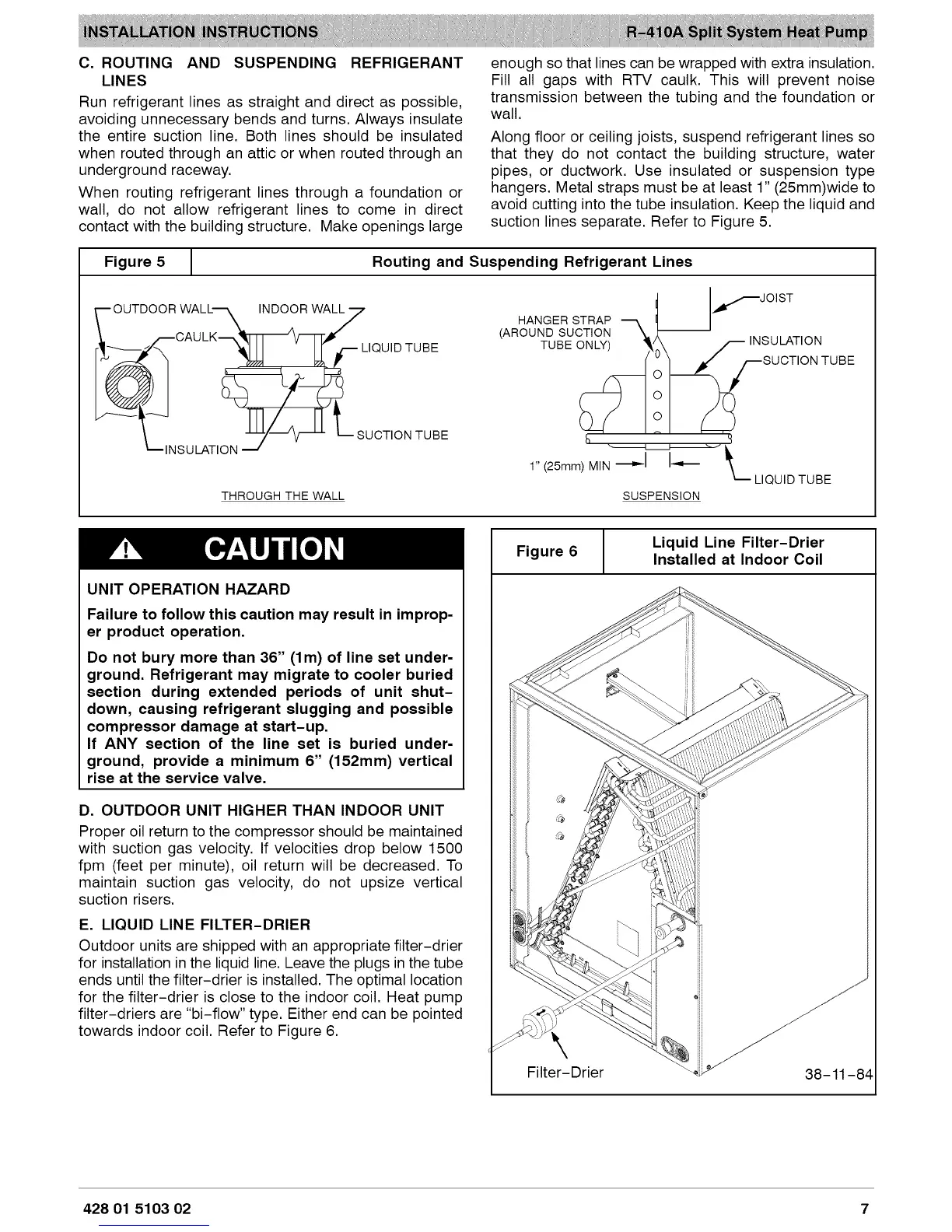
Along floor or ceiling joists, suspend refrigerant lines so
that they do not contact the building structure, water
pipes, or ductwork. Use insulated or suspension type
hangers. Metal straps must be at least 1" (25mm)wide to
avoid cutting into the tube insulation. Keep the liquid and
suction lines separate. Refer to Figure 5.
Figure 5
1
Routing and Suspending Refrigerant Lines
OUTDOOR WALL's, INDOOR WAL_7
I_CAU LK_[-FI_ V_I-F,_"
_ LIQUID TUBE
-- '____N S ULATI ON __/_]- SUCTION TUBE
THROUGH THE WALL
HANGER STRAP
(AROUND SUCTION _,_ --
TUBE ONLY) _'
lf JOiST
t_SU cTLATIoONNTUB E
1" (25mm) MIN "_-J J_
LIQUID TUBE
SUSPENSION
UNIT OPERATION HAZARD
Failure to follow this caution may result in improp-
er product operation.
Do not bury more than 36" (lm) of line set under-
ground. Refrigerant may migrate to cooler buried
section during extended periods of unit shut-
down, causing refrigerant slugging and possible
compressor damage at start-up.
If ANY section of the line set is buried under-
ground, provide a minimum 6" (152mm) vertical
rise at the service valve.
D. OUTDOOR UNIT HIGHER THAN INDOOR UNIT
Proper oil return to the compressor should be maintained
with suction gas velocity. If velocities drop below 1500
fpm (feet per minute), oil return will be decreased. To
maintain suction gas velocity, do not upsize vertical
suction risers.
E. LIQUID LINE FILTER-DRIER
Outdoor units are shipped with an appropriate filter-drier
for installation in the liquid line. Leave the plugs in the tube
ends until the filter-drier is installed. The optimal location
for the filter-drier is close to the indoor coil. Heat pump
filter-driers are "bi-flow" type. Either end can be pointed
towards indoor coil. Refer to Figure 6.
Figure 6
Liquid Line Filter-Drier
Installed at Indoor Coil
428 01 5103 02 7