TECHNICAL SUPPORT MANUAL Split System Heat Pump: N4H3
6 42804510201
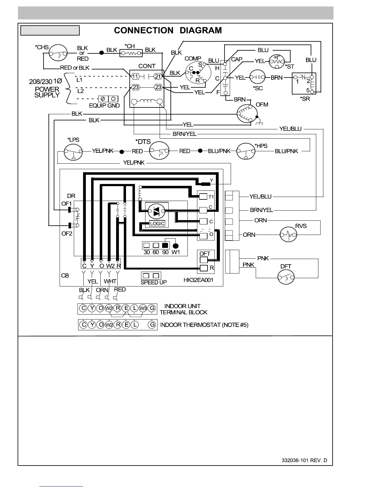
1. Symbols are electrical representation only.
2. Compressor and fan motor furnished with inherent thermal protection.
3. To be wired in accordance with National Electric N.E.C. and local codes.
4. N.E.C. class 2, 24 V circuit, min. 40 VA required, 60 VA on units installed with LLS.
5. Connection for typical heat pump thermostat. For other arrangements see installation instructions.
6. Use copper conductors only. Use conductors suitable for at least 75° C (167° F).
7. If indoor section has a transformer with a grounded secondary, connect the grounded side to “C” on the circuit board.
8. When start capacitor and relay are installed, start thermistor (PTC) is not used.
9. CH not used on all units.
10. If any of the original wire, as supplied, must be replaced, use the same or equivalent wire.
11. Check all electrical connections inside control box for tightness.
12. Do not attempt to operate unit until service valves have been opened.
13. Do not rapid cycle compressor. Compressor must be off 3 minutes to allow pressures to equalize between high and low
side before starting.
Notes:
Model Size: 60
 Loading...