1 .
Fire or explosion hazard.
Turn OFF gas at shut off before connecting U-tube
manometer.
Failure to turn OFF gas at shut off before connecting
U-tube manometer can result in personal injury
and/or death.
With gas OFF, Connect U-Tube manometer to tapped
opening on gas valve. Use manometer with a 0 to rain. 12"
water column range.
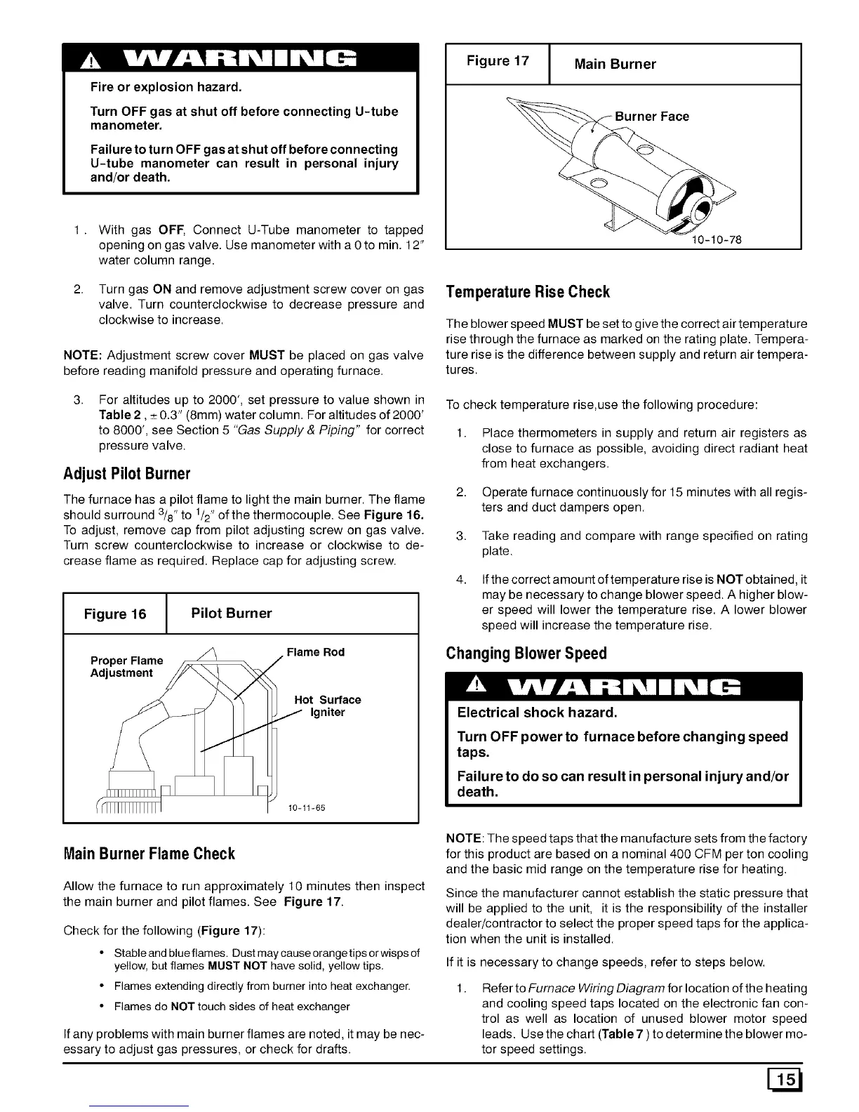
Figure 17 Main Burner
Burner Face
10-10-78
2. Turn gas ON and remove adjustment screw cover on gas
valve. Turn counterclockwise to decrease pressure and
clockwise to increase.
NOTE: Adjustment screw cover MUST be placed on gas valve
before reading manifold pressure and operating furnace.
Temperature Rise Check
The blower speed MUST be set to give the correct air temperature
rise through the furnace as marked on the rating plate. Tempera-
ture rise is the difference between supply and return air tempera-
tures.
For altitudes up to 2000', set pressure to value shown in
Table 2, _+0.3" (8mm) water column. For altitudes of 2000'
to 8000', see Section 5 "Gas Supply & Piping" for correct
pressure valve.
Adjust Pilot Burner
The furnace has a pilot flame to light the main burner. The flame
should surround 3/8" to 1/2"of the thermocouple. See Figure 16.
To adjust, remove cap from pilot adjusting screw on gas valve.
Turn screw counterclockwise to increase or clockwise to de-
crease flame as required. Replace cap for adjusting screw.
Figure 16 Pilot Burner
/_ Flame Rod
Proper Flame _ J
Adjustment /_
i / _"_ Hot Surface
/ _// j ,gniter
10-11-65
To check temperature rise,use the following procedure:
1. Place thermometers in supply and return air registers as
close to furnace as possible, avoiding direct radiant heat
from heat exchangers.
2. Operate furnace continuously for 15 minutes with all regis-
ters and duct dampers open.
3. Take reading and compare with range specified on rating
plate.
4.
If the correct amount of temperature rise is NOT obtained, it
may be necessary to change blower speed. A higher blow-
er speed will lower the temperature rise. A lower blower
speed will increase the temperature rise.
Changing Blower Speed
Electrical shock hazard.
Turn OFF power to furnace before changing speed
taps.
Failure to do so can result in personal injury and/or
death.
Main Burner Flame Check
Allow the furnace to run approximately 10 minutes then inspect
the main burner and pilot flames. See Figure 17.
Check for the following (Figure 17):
• Stable and blue flames. Dust may cause orangetips or wisps of
yellow, but flames MUST NOT have solid, yellow tips.
• Flames extending directly from burner into heat exchanger.
• Flames do NOT touch sides of heat exchanger
If any problems with main burner flames are noted, it may be nec-
essary to adjust gas pressures, or check for drafts.
NOTE: The speed taps that the manufacture sets from the factory
for this product are based on a nominal 400 CFM per ton cooling
and the basic mid range on the temperature rise for heating.
Since the manufacturer cannot establish the static pressure that
will be applied to the unit, it is the responsibility of the installer
dealer/contractor to select the proper speed taps for the applica-
tion when the unit is installed.
If it is necessary to change speeds, refer to steps below.
1.
Refer to Furnace Wiring Diagram for location of the heating
and cooling speed taps located on the electronic fan con-
trol as well as location of unused blower motor speed
leads. Use the chart (Table 7 ) to determine the blower mo-
tor speed settings.