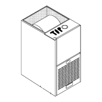
Figure 14 Filter Rack Installation
25-21-05
1.
2.
Insert end of filter rack with 3/4" (19ram) flange into slot in
the back of the unit. See Figure 15.
With filter rack pushed back, insert front end with 1/4"
(6ram) flange into position and push into front slot. with filter
rack pushed as far forward as it will go, bend 1/4"(6mm)
flange and 3/4"(19mm) flange up 90 degrees. See Figure
15.
NOTE: Plenum must be fitted as close to the return air flange of
the unit as possible to eliminate any air bypassing the filters.
3.
Filters can only be installed through the right hand side of
the unit blower opening. Slide filter into unit until it is in posi-
tion to be pushed up and over into place on the left hand
side of unit. See Figure 16.
NOTE: The return air plenum MUST extend a sufficient height
above dimension "A" (Figure 15) to provide for the attachment of
a return air duct or grille above the filters.
4. Slide remaining filter into unit and up into place on left hand
side of unit. See Figure 16.
Figure 15 Filter Installation
A=14"
(350ram)
25-21-06
If there is insufficient plenum height for this type of installation, fil-
ters may be installed in any accessible location in the return air
system. In such a case, the filters should be of equivalent size and
style as originally supplied with the furnace.
Filter Removal
1. Remove cornpartment door.
2. Reach up above right side of blower and lift dirty filters out of
rack at top of furnace.
3. Straighten up filters and pull straight down at side of blower.
Pull out through right door opening.
4. Vacuum clean or wash with warm water and dry thoroughly
before replacing.
Filters
NOTE: The furnace is provided with high velocity type filter(s).
The size, quantity, and type of filter supplied with the furnace will
handle the airflow required if central air conditioning is used with
the furnace.
8. ChecksandAdjustments
Startup
NOTE: Refer to Start-up procedures in the user's inforrnation
manual.
Gas Supply Pressure
Gas supply pressure should be within rninimum and rnaximum
values listed on rating plate. Pressures are usually set by gas sup-
pliers.
CAUTION
If any sparks, odors or unusual noises occur, immediately
shut OFF power to furnace. Check for wiring errors or ob-
struction to blower.
fin
ManifoldGas Pressure Adjustment
NOTE: Make adjustment to manifold pressure with burners oper-
ating.

 Loading...