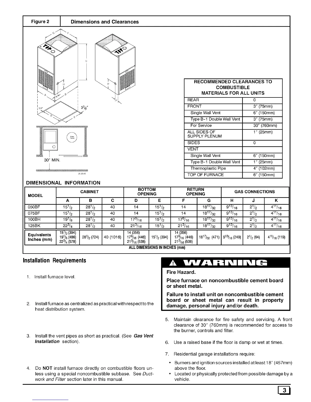
Figure 2 [ Dimensions and Clearances
RECOMMENDED CLEARANCES TO
COMBUSTIBLE
MATERIALS FOR ALL UNITS
REAR 0
FRONT 3" (75mm)
Single Wall Vent 6" (150mm)
Type B-1 Double Wall Vent 3" (75mm)
For Service 30" (760mm)
ALL SIDES OF 1" (25mm)
SUPPLY PLENUM
SIDES 0
VENT
Single Wall Vent 6" (150mm)
Type B-1 Double Wall Vent 1" (25mm)
Thermoplastic Pipe 4" (102mm)
TOP OF FURNACE 6" (150mm)
DIMENSIONAL INFORMATION
MODEL
050BF
075BF
100BH
125BK
Equivalents
Inches (mm)
A
t51/2
t51/2
t91/6
223/4
I 151/2 394
19118(486)
223/4(578)
CABINET
B
281/2
281/2
281/2
281/2
281/2(724)
BOTTOM
OPENING
D E
14 151_
14 151_
17_16 151_
2t_16 151_
151_ (394)
RETURN
C
40
40
40
40
I 14(356)
40 (1016) 179/16(446)
213/16(538)
GAS CONNECTIONS
H
913/16
913/16
913/16
913/16
OPENING
F G
t4 1817/32
t4 1817/32
179/16 1817/32
213/16 1817/32
14 (356) I
179/16(446) I 1817/32(47t)213/16(538)
ALL DIMENSIONSIN INCHES(ram)
Fire Hazard.
913/16 (249)
J
21/2
21/2
21/2
21/2
21/2(64)
Installation Requirements
K
411/16
411/16
411/16
411/16
411t16(119)
1. Install furnace level.
Install fu mace as centralized as practical with respect to the
heat distribution system.
Place furnace on noncombustible cement board
or sheet metal.
Failure to install unit on noncombustible cement
board or sheet metal can result in property
damage, personal injury and/or death.
Install the vent pipes as short as practical. (See Gas Vent
Installation section).
5. Maintain clearance for fire safety and servicing. A front
clearance of 30" (760mm) is recommended for access to
the burner, controls and filter.
6. Use a raised base if the floor is damp or wet at times.
Do NOT install furnace directly on combustible floors un-
less using a special noncombustible subbase. See Duct-
work and Filter section later in this manual.
7. Residential garage installations require:
• Burners and ignition sources installed at least 18" (457mm)
above the floor.
• Located or physically protected from possible damage by a
vehicle.
G3