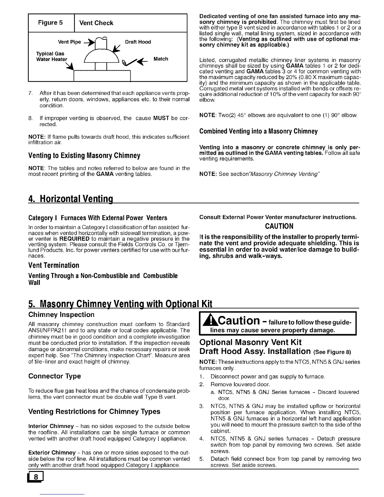
Figure 5 Vent Check
Vent Pipe "-_ I A/ Draft Hood
Typical Gas
Water Heater
! I
Match
7. After it has been determined that each appliance vents prop-
erly, return doors, windows, appliances etc. to their normal
condition.
8. If improper venting is observed, the cause MUST be cor-
rected.
NOTE: If flame pulls towards draft hood, this indicates sufficient
infiltration air.
Venting to ExistingMasonry Chimney
NOTE: The tables and notes referred to below are found in the
most recent printing of the GAMA venting tables.
Dedicated venting of one fan assisted furnace into any ma-
sonry chimney is prohibited. The chimney rnust first be lined
with either type B vent sized in accordance with tables 1 or 2 or a
listed single wall, metal lining system, sized in accordance with
the following: (Venting as outlined with use of optional ma-
sonry chimney kit as applicable.)
Listed, corrugated metallic chimney liner systems in masonry
chimneys shall be sized by using GAMA tables 1 or 2 for dedi-
cated venting and GAMA tables 3 or 4 for common venting with
the maximum capacity reduced by 20% (0.80 X maximum capac-
ity) and the minimum capacity as shown in the applicable table.
Corrugated metal vent systems installed with bends or offsets re-
quire additional reduction of 10% of the vent capacity for each 90°
elbow.
NOTE: Two(2) 45 ° elbows are equivalent to one (1 90° elbow.
Combined Venting into a Masonry Chimney
Venting into a masonry or concrete chimney is only per-
mitted as outlined in the GAMA venting tables. Follow all safe
venting requirernents.
NOTE: See section"Masonry Chimney Venting"
4. HorizontalVenting
Category I Furnaces With External Power Venters
Inorder to maintain a Category][ classification offan assisted fur-
naces when vented horizontally with sidewall termination, a pow-
er venter is REQUIRED to maintain a negative pressure in the
venting system. Please consult the Fields Controls Co. or Tjern-
lund Products, Inc. for power venters certified for use with our fur-
naces.
Vent Termination
Venting Through a Non-Combustible and Combustible
Wall
Consult External Power Venter manufacturer instructions.
CAUTION
It isthe responsibility of the installer to properly termi-
nate the vent and provide adequate shielding. This is
essential in order to avoid water/ice damage to build-
ing, shrubs and walk-ways.
5. MasonryChimneyVentingwithOptionalKit
Chimney Inspection
All masonry chirnney construction must conform to Standard
ANSI/NFPA211 and to any state or local codes applicable. The
chimney must be in good condition and a complete investigation
must be conducted prior to installation. If the inspection reveals
damage or abnormal conditions, make necessary repairs or seek
expert help. See "The Chimney Inspection Chart". Measure area
of tile-liner and exact height of chimney.
Connector Type
To reduce flue gas heat loss and the chance of condensate prob-
lems, the vent connector must be double wall Type B vent.
Venting Restrictions for Chimney Types
Interior Chimney - has no sides exposed to the outside below
the roofline. All installations can be single furnace or common
vented with another draft hood equipped Category ][appliance.
Exterior Chimney - has one or more sides exposed to the out-
side below the roof line. All installations must be common vented
only with another draft hood equipped Category ][appliance.
I, kCa ution - failure to follow these guide- I
lines may cause severe property damage.
Optional Masonry Vent Kit
Draft Hood Assy. Installation (SeeFigure8)
NOTE: These instructions apply to the NTC5, NTN5 & GNJ series
furnaces only.
1. Disconnect power and gas supply to furnace.
2. Remove Iouvered door.
a. NTC5, NTN5 & GNJ Series furnaces - Discard Iouvered
door.
3. NTC5, NTN5 & GNJ may be installed upflow or horizontal
position per furnace application. When installing NTC5,
NTN5 & GNJ furnaces in a horizontal left hand application
you will need to mount the pressure switch to the side of the
cabinet.
4. NTC5, NTN5 & GNJ series furnaces - Detach pressure
switch from top panel by removing two screws. Set aside
screws.
5. Detach field connect box from top panel by removing two
screws. Set aside screws.