RDA5807 FM 87-108MHz Radio Receiver LCD1602 DIY Kit
6
Step 26: Install 4pcs 6*6*20mm Black Button atS1, S2, S3, S5.
Step 27: Install 1pcs DIP-8 IC LM386N at U3.
There is a gap mark on one end of the IC and there is a gap mark on DIP-8
IC Socket where the IC can place on.
These two marks are corresponding to each other and are used to specify
the installation direction of the IC.
Step 28: Install 1pcs DIP-40 IC STC89C52RC.
There is a gap mark on one end of the IC and there is a gap mark on
DIP-40 IC Socket where the IC can place on.
These two marks are corresponding to each other and are used to specify
the installation direction of the IC.
Step 29: Fix 4pcs M3*10mm Copper Pillar and 4pcs M3*8mm Screw on
PCB.
Step 30: Install 1pcs 16Pin Male Socket on the black of LCD1602 display
screen.
Step 31: Plug LCD1602 display screen on 16Pin DuPont Female Socket.
Note: Don't use screws to fix it for now.
Step 32: Install 1pcs 75ohm Antenna at ANT. Keep a distance more than
5mm from PCB and fix by tin(not screw). Note: the antenna should be installed
on the back of the PCB.
Step 33: Place 2pcs red button cap on Self-locking Button.
Step 34: Connect speaker to PCB at SP by 20cm red/black Cable. The
speaker does not distinguish between positive and negative.
Step 35: Tear off the protective film on the surface of the acrylic shell.
Step 36: Fix Top Acrylic Board and LCD1602 Acrylic Board on Copper
Pillar by 4pcs M3*6mm Screw.
Step 37: Fix 4pcs Side Acrylic Board by 6pcs M3*6mm Screw and 6pcs
M3 Nuts.
Step 38: Fix speaker on Acrylic Bottom Board by 4pcs M3*10mm Screws
and 4pcs M3 Nuts.
Step 39: Install Speaker Acrylic Board by 4pcs M3*6mm Screw and 4pcs
M3 Nuts.
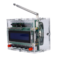
Step 40: Connect to power supply and enjoy the effect.
10.Install shown steps by steps: