Do you have a question about the ICStation RDA5807 and is the answer not in the manual?
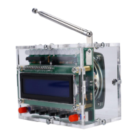
Overview of the FM Radio Receiver DIY Kit with RGB spectrum indicator and LCD display.
Highlights include volume adjustment, RGB spectrum indicator, frequency support, and 5W amplifier.
Details operating voltage, output power, receiver frequency, and accuracy.
Instructions on using the left button to control the power supply.
Instructions for adjusting spectrum indicator, volume, and tuning frequency using buttons.
Detailed circuit diagram illustrating the connections and components of the receiver.
Advice on signal interference, SMD component handling, and tool preparation.
Steps for installing the RDA5807 FM Receiver, crystal oscillator, and IC sockets.
Guidance on installing various metal film resistors at designated PCB locations.
Steps for installing capacitors, KA2284 LED driver, and identifying LED polarity.
Installation of DuPont socket, antenna, buttons, and power socket.
Installation of other ICs, buttons, and securing the PCB with pillars and screws.
Connecting LCD, speaker, and assembling the acrylic shell.
This document describes the RDA5807 FM 87-108MHz Radio Receiver LCD1602 DIY Kit, a self-assembly kit designed for enthusiasts to build their own FM radio receiver. The kit features an RGB spectrum indicator that flashes automatically and a blue LCD1602 display screen for clear frequency indication.
The RDA5807 FM Radio Receiver DIY Kit allows users to construct a functional FM radio. It incorporates a built-in volume adjustment, an RGB spectrum indicator for visual feedback, and a 5W power amplifier for audio output. The device supports a receiver frequency range of 87.0MHz to 108.0MHz, enabling reception of standard FM radio stations. The LCD1602 display screen provides a clear visual representation of the currently tuned frequency.
The kit's operation is straightforward:
The RDA5807 FM 87-108MHz Radio Receiver LCD1602 DIY Kit boasts several key technical parameters:
The kit includes a comprehensive list of components necessary for assembly, such as various metal film resistors (10ohm, 100ohm, 6.8Kohm, 1Kohm, 10Kohm), the RDA5807 FM Receiver (SMD), a crystal oscillator (11.0592MHz), IC sockets (DIP-8, DIP-40), ceramic capacitors (22pF), monolithic capacitors (0.1uF 104), KA2284 LED drivers (ZIP-9), RGB LEDs (5mm), DuPont female and male sockets (16Pin), electrolytic capacitors (4.7uF, 100uF), a DC-005 power socket (5.52.5mm), self-locking buttons (5.85.8mm) with red caps, black buttons (6620mm), an LM386N IC (DIP-8), an STC89C52RC IC (DIP-40), an LCD1602 display screen (blue), a 75ohm antenna (25cm), a 4ohm 5W speaker (22mm), red/black speaker wire (20cm), and a USB-DC005 power wire (100cm). Mechanical components include an acrylic board, M310mm copper pillars, M310mm, M38mm, and M36mm screws, and nuts. The PCB itself measures 82641.6mm.
The RDA5807 FM Radio Receiver is designed for ease of use once assembled. Its compact size (907055mm) makes it portable. The blue LCD1602 display ensures that the current frequency is always visible. The RGB spectrum indicator adds a dynamic visual element to the listening experience, flashing automatically to enhance user engagement. The built-in 5W power amplifier provides sufficient audio output for personal listening.
As a wireless module, it is important to note that the device should not be used in environments with significant signal interference to ensure optimal reception quality.
The kit is primarily a DIY assembly project, and maintenance largely revolves around proper installation and handling of components.
The installation process is detailed step-by-step, covering the placement and soldering of each component, from the RDA5807 FM Receiver SMD to the final assembly of the acrylic casing and speaker. This detailed guidance aims to minimize errors and ensure a successful build.