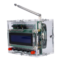
RDA5807 FM 87-108MHz Radio Receiver LCD1602 DIY Kit
4
1.2>.Rosin core ("radio") solder
1.3>.Wire cutters
1.4>.Wire strippers
1.5>.Philips screwdriver
2>.The soldering iron can't touch the components for a long time(1.0
second), otherwise it will damage the components.
3>.Pay attention to the positive and negative of the components.
4>.Strictly prohibit short circuit.
5>.User must install the LED according to the specified rules.Otherwise
some LED will not light.
6>.Install complex components preferentially.
7>.Make sure all components are in right direction and right place.
starting installation!!!
8>.Please wear anti-static gloves or anti-static wristbands when installing
electronic components.
9. Installation Steps(Please be patient):
Step 1: Install 1pcs SMD components RDA5807 FM Receiver at U2.
Verify and confirm the installation direction of RDA5807.
The rectangular silk screen on the PCB coincides with the crystal
oscillator on the RDA5807 to locate the installation direction.
Step 2: Randomly choose a pad on the PCB, and then melt the solder on
this pad.
Step 3: Fix RDA5807: Use a soldering iron to melt tin on the pad just now
and hold RDA5807 with tweezers in the other hand to place/press on U2 to
prevent movement.
Take care to match and align each pads. Then remove soldering iron.
Then remove tweezers after solder tin cooling and solidification.
Step 4: Connect others pads on RDA5807 to pads on PCB by tin and
soldering iron.
Step 5: Install 1pcs 10ohm Metal Film Resistor at R6.
Step 6: Install 2pcs 100ohm Metal Film Resistor at R19, R20.
Step 7: Install 2pcs 6.8Kohm Metal Film Resistor at R12, R15.
Step 8: Install 4pcs 1Kohm Metal Film Resistor at R9, R13 ,R16, R17.
Step 9: Install 11pcs 10Kohm Metal Film Resistor at R1-R5, R7, R8, R11,
R14, R15, R18.
Step 10: Install 1pcs 11.0592MHz Crystal Oscillator at Y1.
Step 11: Install 1pcs DIP-8 IC Socket at U3.
There is a gap mark on one end of the IC Socket and there is a gap mark
on PCB silk screen where the IC Socket can place on.
These two marks are corresponding to each other and are used to specify
the installation direction of the IC Socket.
 Loading...
