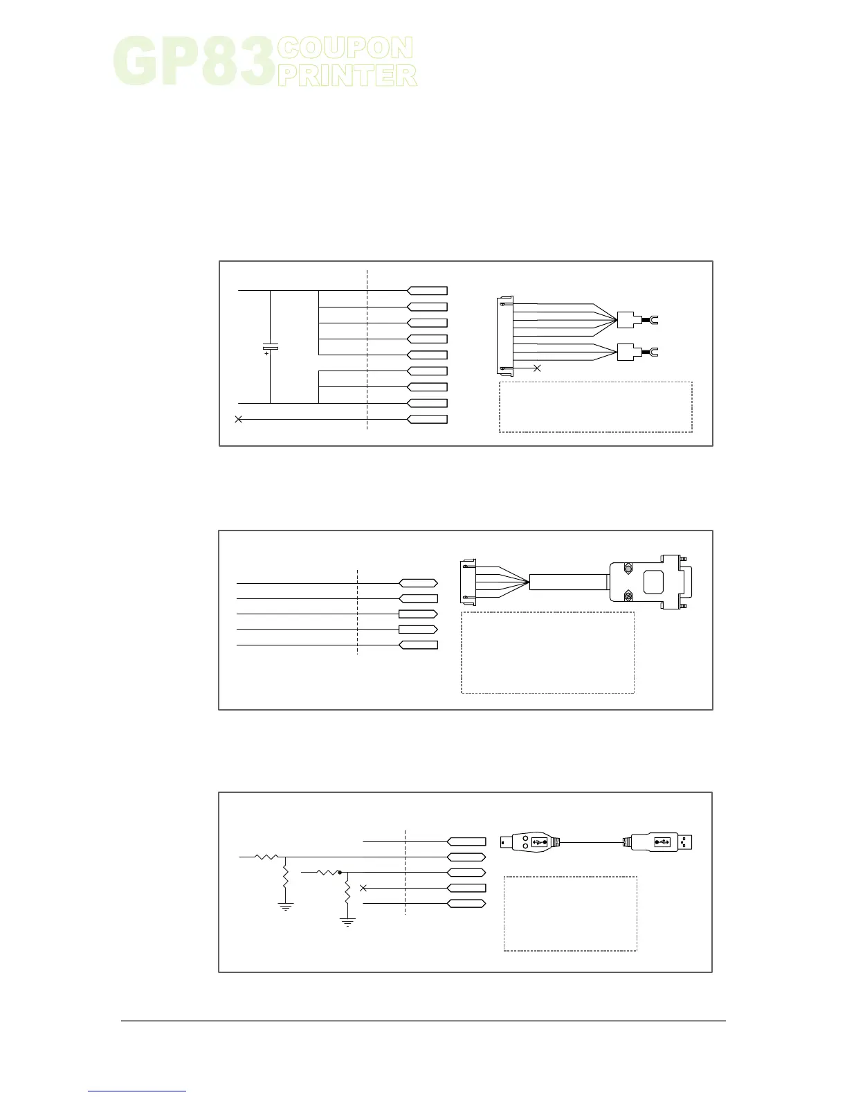
3-3. I/O Circuits
Chapter 3
19
www.ictgroup.com.tw
Control Board I/O Circuits
CN1 CONNECTER PIN
POWER
PIN 1~PIN 5- BLACK......POWER GROUND
PIN 6~PIN 8- RED................POWER(+24V)
WEL-RG808
Y(3.2Φ)
Y(3.2Φ)
1
2
3
4
5
6
7
8
9
PIN1
PIN2
PIN3
PIN4
PIN5
PIN6
PIN7
PIN8
PIN9
GND
+24V
GND
GND
GND
GND
GND
+24V
+24V
+24V
NC
CN7 CONNECTER PIN
PIN1
PIN2
PIN3
PIN4
PIN5
GND
TXD
RXD
CTS
RTS
GND
TXD
RXD
CTS
RTS
WEL-RG807
D-SUB(F)
1
2
3
4
5
RS-232
PIN 1- YELLOW.....POWER GROUND
PIN 2- ORANGE...........................TXD
PIN 3- RED.................................. RXD
PIN 4- BROWN.............................CTS
PIN 5- BLACK...............................RTS
CN9 CONNECTER PIN
PIN1
PIN2
PIN3
PIN4
PIN5
D+
D-
+3.3V
GND
3.3V
D-
D+
NC
GND
R
R
R
R
MINI USB 5P
USB-A-TYPE
WEL-RG809
USB
PIN1:USB3.3V
PIN2:USB D-
PIN3:USB D+
PIN5:POWER GROUND
Figure 13
Figure 14
Figure 15
 Loading...