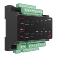
The Protege Half DIN Rail 2 Door Reader Expander (PRT-HRDM-DIN) is a flexible module designed to extend the number of card reader inputs in a security system. It supports two doors when using multiple reader mode, with four inputs used for door monitoring and control, and eight outputs. The module is designed for integration into a DIN rail network, allowing for large numbers of modules to be connected to the RS-485 module network. It can support up to 250 modules and a network repeater module can extend the distance up to 900M (3000ft).
Function Description
The PRT-HRDM-DIN serves as a reader expander, providing access control for two doors (entry or entry/exit) when configured in multiplex mode. It supports 4 Wiegand devices controlling 2 doors, giving flexibility for entry and exit readers. The two reader ports can be independently configured to connect RS-485 readers.
Key features include:
- 4 Wiegand reader mode for 2 entry/exit doors per reader expander: Allows for flexible reader configurations.
- 4 RS-485 reader mode for 2 entry/exit doors per reader expander: Supports RS-485 communication for readers.
- Secure encrypted RS-485 module communications: Ensures secure data transmission within the network.
- 8 inputs: Four inputs are dedicated for door monitoring and control, with additional inputs for general purpose use.
- 2 lock Form C Relay outputs: Provides control for electric door strikes and other lock control devices.
- 6 open collector outputs (reader control outputs): Used to activate bell sirens, lighting circuits, relay accessory products, and other automation points.
- Smart reader missing/tamper monitoring: Enhances security by detecting issues with connected readers.
- Offline functions including All Users, First 10 Users plus 150 Card Cache and No Users: Allows for continued operation even if the module loses network connection.
- Online and remote upgradeable firmware: Facilitates easy updates and maintenance.
- Industry-standard DIN rail mounting: Simplifies installation and integration into existing systems.
Important Technical Specifications
- Power Supply: 11-14VDC input voltage.
- DC Output Voltage (DC In Pass Through): 10.83-14.0VDC 0.7A (Typical) Electronic Shutdown at 1.1A. Reader 1&2 10.45-13.85VDC Pass Through share 0.7A (Typical) Electronic Shutdown at 1.1A.
- Operating Current: 80mA (Normal Standby).
- Total Combined Current*: 1.6A (Max).
- Low Voltage Cutout: 8.7VDC.
- Low Voltage Restore: 10.5VDC.
- Communication: RS-485 module network.
- Offline Operation: All Users, First 10 Users plus 150 Card Cache, No Users.
- Reader Configurations: 2 reader ports that can be independently configured for either Wiegand (up to 1024 bits configurable) or RS-485, allowing connection of up to 4 readers providing entry/exit control for two doors. RS-485 reader port connections support configuration for OSDP protocol.
- Lock Outputs: 2 Form C Relay Outputs - 7A N.O./N.C. at 30 VAC/DC resistive/inductive.
- Outputs: 6 (50mA Max) Open Collector.
- Inputs: 8 High Security Monitored Inputs (10ms to 1hr Input Speed Programmable).
- Trouble Inputs: 16.
- Dimensions (L x W x H): 78 x 90 x 60mm (3.07 x 3.54 x 2.36").
- Net Weight: 210g (7.4oz).
- Gross Weight: 270g (9.5oz).
- Operating Temperature: UL/ULC 0° to 49°C (32° to 120°F); EU EN -10° to 55°C (14° to 131°F).
- Storage Temperature: -10° to 85°C (14° to 185°F).
- Humidity: 0%-93% non-condensing, indoor use only (relative humidity).
- Mean Time Between Failures (MTBF): 622,997 hours (calculated using RFD 2000 (UTE C 80-810) Standard).
* The total combined current refers to the current that will be drawn from the external power supply to supply the expander and any devices connected to its outputs. The auxiliary outputs are directly connected via thermal resettable fuses to the N+ input terminals, and the maximum current is governed by the trip level of these fuses.
** Each reader port supports either Wiegand or RS-485 reader operation, but not both at the same time. If combining reader technologies, they must be connected on separate ports.
Usage Features
- Mounting: The module is designed for standard DIN rail mounting. It can be mounted in dedicated DIN cabinets or on generic DIN rail mounting strip. Proper clearance around all sides of the device is required for adequate air flow. The module should be installed in an electrical room, communication equipment room, secure cabinet, or an accessible area of the ceiling.
- Position the DIN rail module with the labeling in the correct orientation.
- Hook the mounting tabs (opposite the tab clip) under the edge of the DIN rail.
- Push the DIN rail module against the mount until the tab clips over the rail.
- Removal:
- Insert a flat blade screwdriver into the hole in the module tab clip.
- Lever the tab outwards and rotate the unit off the DIN rail mount.
- Grounding: Proper grounding is essential for safety and to prevent damage from elevated voltages. The module requires a single-point earth ground connection. A minimum 14AWG solid copper wire (or thicker, in accordance with local authorities) should be used from the Protege system’s earth connection points. The DIN rail enclosure includes an earth ground single-point link connection via the metallic enclosure. All modules that have earth ground connections and that are installed in the same enclosure shall be connected to this single point. A single-point earth ground connection avoids the creation of ground loops in the system and provides a single reference point to earth ground.
- DC Power & Encrypted Module Network: The expander uses encrypted RS-485 communications. Both module and network power are supplied by the N+ and N- terminals. The 12V N+ and N- communication input must be supplied from only one point. Connections from more than one 12V supply may cause failure or damage. A 330 ohm EOL (End of Line) resistor must be inserted between the NA and NB terminals of the first and last modules on the RS-485 network.
- Door Access Control: The reader expander provides access control functionality without the requirement for additional hardware. It supports Belden 9842 or equivalent, and 24 AWG twisted pair with characteristic impedance of 120ohm for RS-485. For Wiegand, it supports 22 AWG alpha 5196, 5198, 18 AWG alpha 5386, 5388.
- Wiring Precautions: The card reader must be connected to the module port using a shielded cable. The shield must only be connected at one end of the cable in the metallic enclosure (frame grounded). Do not connect the cable shield to an AUX+, 0V or V- connection on the module. Do not connect the cable shield to any shielded for isolated communication. The reader and cable shield wires must be joined at the reader pigtail splice. Do not join the shield and black wires at the reading device. Do not terminate the reader shield wire inside the reader.
- Reader and Cable Shield Wires: These must be joined at the reader pigtail splice for all MIFARE capable ICT card readers. Older readers which are internally grounded and third-party readers do not require the shield wires to be joined.
- RS-485 Reader Locations:
- Entry: Green and orange wires not connected.
- Exit: Green and orange wires connected together.
- Wiegand Reader Connection: The module supports standard Wiegand reader connection with single LED and dual LED operation. Dual LED operation allows the signaling of both LEDs independently using the LED control lines, and is ideal to show the status of alarm or other integrated signals. Readers must also be programmed to operate in dual LED mode.
- Multiple Wiegand Reader Connection: In multiple reader mode, the secondary reader has all connections wired to the same port as the primary card reader, with the DATA 1 connection wired to the opposite reader connection DATA 1 input. The reader that is multiplexed into the alternate reader port will operate as the exit reader, and the normal reader connection operates as the entry reader.
- Magnetic Reader Connection: The reader expander allows the connection of standard magnetic track 2 format cards and provision is made in the software for a large number of formats. Formats include BIN number for ATM access control and first 4, 5 and 6 card numbers. Magnetic card readers are typically operated by 5 volts. Before connecting the magnetic card reader to the reader expander, ensure that the supply voltage is correct and if required insert the inline 5 volt regulator.
- Door Contact Connection: The module allows the connection of up to 4 contacts for monitoring and controlling access control doors. Each input can be used for either the door function that is automatically assigned or as a normal input on the system. The following example shows the connection of a normally closed door position monitoring contact to monitor the open, closed, forced and alarm conditions of the door.
- Door Lock Connection: The reader expander provides two lock output relays that can be used to switch electric locks. When using a door with an entry and exit reader on separate reader ports, the lock output should be connected to LOCK 1, and enable the Swap Lock LED Display option for the second reader input to allow the reader LEDs to display the correct status. The 1N4007 diode shown in the diagram is supplied with the reader expander and must be installed at the electric strike terminals.
- Inputs: The reader expander can monitor the state of up to 8 inputs. These inputs can be connected to a variety of EOL monitored dry contact devices such as magnetic switches and PIR motion detectors. Devices connected to the inputs can be installed to a maximum distance of 300m (1000ft) from the module when using 22 AWG wire. Each input may be individually configured for normally opened and normally closed configurations with or without EOL resistors for tamper and short condition monitoring.
- Magnetic contacts shall be listed to UL 634 to comply with UL installation standards and ULC/ORD-C634 to comply with ULC installation standards.
- Motion detectors and temperature sensors shall be listed to UL 639 to comply with UL installation standards and ULC-S306 to comply with ULC installation standards.
- The reader expander has been evaluated for UL 294 and CAN/ULC-S319 standalone access control.
- When using an input with the EOL resistor configuration, the controller generates an alarm condition when the state of an input changes between open and closed and generates a tamper alarm condition when a wire fault (short circuit) or a cut wire (tampered) in the line occurs.
- When using the EOL resistor configuration, the EOL resistor option must be enabled in the input programming so that the tamper and short states can be monitored.
- Trouble Inputs: Each reader expander can monitor up to 16 trouble inputs used to report trouble conditions such as module communications problems. Trouble inputs are used to monitor the module status and in most cases are not physically connected to an external input.
- Door Trouble Inputs: In addition to the trouble inputs of the module itself, the reader expander can also monitor trouble inputs associated with connected doors. These are used for monitoring and reporting door troubles such as door forced and duress conditions.
- Outputs: The reader expander has 8 programmable outputs. These outputs are used to activate bell sirens, lighting circuits, door locks, relay accessory products and other automation points.
- Lock Outputs (1 and 2): Relays are provided on outputs 1 and 2. These are used for the Lock 1 (Output 1 RD001:01) and Lock 2 (Output 2 RD001:02) functions and are used to control electric door strikes and other lock control devices. The relay outputs can switch to a maximum capacity of 7A. Exceeding this amount will damage the output.
- Standard Outputs (3 To 8): Outputs 3, 4, 5, 6, 7 and 8 on the reader expander are open collector outputs and switch to a ground connection. These outputs have a default pre-programmed function as detailed in the table and are used to control the indicator and audible outputs on the attached reading device. These functions may be disabled by programming the appropriate setting in the reader expander configuration.
- Beeper Outputs (5 and 8): The beeper outputs 5 and 8 on the reader expander provide diagnostic information to the end user and installer when a card is presented and access is denied or the unit is operating offline.
- Address Configuration: The module address is configured via programming and will require knowledge of the module serial number. The serial number can be found on the identification sticker on the product. Refer to the Protege system controller installation manual for address programming details. The controller has a set limit on the number of modules of each type that it can support. When adding and configuring modules always refer to the Maximum Module Addresses table in the controller installation manual.
- LED Indicators: Protege DIN rail modules feature comprehensive diagnostic indicators that can aid the installer in diagnosing faults and conditions. In some cases an indicator may have multiple meanings depending on the status indicator display at the time.
- Status Indicator: Fast flash (green) for module attempting registration with controller. Slow flash (green) for module successfully registered with controller. Flashing (red) for module communications activity.
- Fault Indicator: Continuous slow flash (red) for module in boot mode awaiting firmware update. Constantly on (red) for module in error state and will flash an error code with the status indicator.
- Power Indicator: Constantly on (green) for correct module input voltage applied. Constantly off for incorrect module input voltage applied.
- Relay Indicators: Constantly on (red) for relay output is ON. Constantly off for relay output is OFF.
- Reader 1/Reader 2 Indicators: Short Flash (red) for a short flash (<250 Milliseconds) on the reader 1/reader 2 indicators will show that data was received but was not in the correct format. Long Flash (red) for a long flash (>1 Second) indicates that the unit has read the data and the format was correct.
- Input Indicators: Constantly off for input is not programmed. Constantly on (red) for input is in an open state. Constantly on (green) for input is in a closed state. Continuous flash (red) for input is in a tamper state. Continuous flash (green) for input is in a short state.
- Error Code Indication: The module attempts to register or communicate with the system controller a registration error can be generated indicating that it was not successful. The following table is only valid if the fault indicator is constantly on and the status indicator is flashing red. If the fault indicator is flashing the module requires a firmware update or is currently in firmware update mode. The status indicator will flash red with the error code number. The error code number is shown with a 250ms on and off period (duty cycle) with a delay of 1.5 seconds between each display cycle.
Maintenance Features
- Firmware Updates: The module supports online and remote upgradeable firmware, allowing for easy updates to address bugs or add new features. If the fault indicator is flashing, the module requires a firmware update or is in firmware update mode.
- Diagnostic Indicators: Comprehensive LED indicators provide visual cues for diagnosing faults and conditions, simplifying troubleshooting.
- Trouble Inputs: The system monitors various trouble conditions, including module communications problems, reader missing/tamper, door forced, and duress conditions, which aids in proactive maintenance and security.
- Error Code Display: Specific error codes are displayed via the status indicator, providing detailed information about issues such as unknown error codes, firmware version incompatibility, address too high, address in use, controller secured registration not allowed, serial number fault, and locked device. This helps in quickly identifying and resolving problems.
- Compliance: The device complies with various international standards, including UL, ULC, EN, UKCA, FCC, and Industry Canada, ensuring its reliability and safety.
- Installation Requirements: Installation must be in accordance with product installation instructions and relevant standards such as UL 681, UL 827, CAN/ULC-S301, CAN/ULC-S302, CAN/ULC-S561, National Electrical Code, Canadian Electrical Code, and AS/NZS 2201.1.
- UL/ULC Installation Cabinet Options: The module must be mounted within the enclosure (refer to UL/ULC Installation Cabinet Options), installed inside the protected premise, and are CAN/ULC-S319 Listed for Class 1 applications only. All cabinet internal covers and lids/doors must be connected to the cabinet’s main ground point for electrical safety and static discharge protection.
- CAN/ULC-S319: For the Protege controller and reader expander module, all RS-485 and reader terminal connections must be made using shielded grounded cable. All readers must be connected with shielded, grounded cable. A bell or visual indicator used as an arming acknowledgment signal must be listed to a UL security, signaling or fire standard. If intended to be mounted outside, it must be rated for outdoor use. Fail secure locking mechanism shall only be installed where allowed by the local authority having jurisdiction (AHJ) and shall not impair the operation of panic hardware and emergency egress. If fire resistance is required for door assembly, portal locking device(s) must be evaluated to UL10B or UL10C. Must be installed with UL/ULC listed electronic locks for UL installations. AC power can shall be indicated by an external panel mount LED (Lumex SSI-LXLH312GD-150) and fitted into a dedicated 4mm hole in the cabinet to provide external visibility. This shall be wired between 12V and a PGM output that is programmed to follow the AC trouble input. If a flexible cord is used to connect to line voltage, strain relief must be provided for the cord inside the enclosure or at the knockout. The power supply is not intended to be mounted on the exterior of vault, safe, or stockroom.
- UL294: The Protege controller and reader expander module are intended to be mounted within the enclosure (refer to UL/ULC Installation Cabinet Options), installed inside the protected premise, and are UL 294 Listed for Attack Class I applications only. Exit devices and wiring must be installed within the protected area.
- Anti Masking: To comply with EN 50131-1 Grade 3 or 4 for Anti Masking, detectors with a separate or independent mask signal should be used and the mask output should be connected to another input. Use 2 inputs per detector. One input for alarm/tamper and one input for masking.
- EN 50131-1: Do not fit more than 10 unpowered detectors per input. Do not fit more than one non-latching powered detector per input. Do not mix unpowered detectors and non-latching powered detectors on an input.
- EN 50131-1 the Entry Timer: The module must be programmed to be more than 45 seconds.
- EN 50131-1 the Bell Cut-Off Time: The module must be programmed between 02 and 15 minutes.
- EN 50131-1 ensures that detectors with LEDs: The LEDs shall only be enabled during Walk Test. This is most conveniently achieved by using detectors with a Remote LED Disable input.
- EN 50131-1, EN 60839-11 Security Grade 4 and AS/NZS2201.1 class 485 Vibration Detection for PreTamper Alarm: Protection is provided by a DSC SS-102 Shockgard Seismic vibration sensor mounted within the system enclosure. Alarm output is by a pair of non-latching, N.C. (normally closed) relay contacts, opening for a minimum of 0.5 second on detection of an alarm connected in series with the 24hr tamper input (TP) on the PSU for any other system input designed/programmed as a 24HR “Tamper Alarm”.
- EN 50131-1: This relay is normally energized to give fail-safe operation in the event of a power loss. Indication of detection is provided by a LED situated on the front cover. The vibration sensor is fully protected from tampering by a N.C. micro switch operated by removal of the cover.
- Enclosure EN-DIN-24: Has been tested and certified to EN50131.
- EN-DIN-11, EN-DIN-12 and EN-DIN-24-ATTACK: Comply with the DIN 50131 standards. Tamper protection against removal of the cover as well as removal from mounting is provided by a tamper switch.
- Warning: Enclosures supplied by 3rd parties may not be EN50131-compliant, and should not be claimed as such.