EasyManua.ls Logo

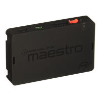
iDataLink maestro Rr ADS-MRR User Manual

iDataLink maestro Rr ADS-MRR
37 pages
To Next Page IconTo Next Page
Page #1 background imageLoading...
Page #1 background image
Revision Date
20130301
Document numbeR
notice The manufacturer will accept no responsability for any electrical
damage resulting from improper installation of this product, be that either
damage to the vehicle itself or to the installed device. This device must be
installed by a certified technician. This guide has been written for properly
trained technicians; a certain level of skill & knowledge is therefore assumed.
Please review the Installation Guide carefully before beginning any work.
beFoRe instaLLation
1- Connect the module to computer
2- Login to Weblink account
3- Flash firmware to module (module is not preloaded with firmware)
4- Use needed accessories
instaLL guiDe
ADSRRSRFOR01DS2IGEN
haRDwaRe
ADSMRR
accessoRies
ADSHRNSRFOR01 OPTIONAL
FiRmwaRe
ADSRRSRFOR01DS2EN
www.maestro.idatalink.comAutomotive Data Solutions Inc. © 2013
11061
Question and Answer IconNeed help?

Do you have a question about the iDataLink maestro Rr ADS-MRR and is the answer not in the manual?

iDataLink maestro Rr ADS-MRR Specifications

General IconGeneral
BrandiDataLink
Modelmaestro Rr ADS-MRR
CategoryCar Amplifier
LanguageEnglish

Summary

Module Overview and Pinouts

Main Module Connectors (A, B, C)

Details for primary module connectors A, B, and C, including pin assignments and functions.

Auxiliary Module Connectors (D-H)

Details for secondary module connectors D through H, covering various functions and pin assignments.

Module Programming Procedure

Initial Setup Steps

Covers steps 01-07: door opening, key insertion, ACC position, Ford setup, and initial completion.

Module Operation and Confirmation

Covers steps 08-11: starting module, continuing, and key cycles for operation.

Repetition and Finalization

Covers steps 12-13: repeating procedures and confirming final programming completion.

Module Reset Procedure

Reset Preparation

Steps 01-03: turn ignition OFF, disconnect module, and press programming button.

LED Status Indicators

Steps 04 & 06: describes LED behavior (RED flash, GREEN solid) during reset process.

Reset Completion

Steps 05 & 07: release button and confirm that module reset procedure is complete.