01
>>
02
6
5
4
3
2
1
7
12V
6
03
04
6
5
4
3
2
1
7
SWI-1
1
05
6
5
4
3
2
1
7
SWI-F
5
06
6
5
4
3
2
1
7
SWI-2
3
07
6
5
4
3
2
1
7
SWI-F
5
>>
>>
08
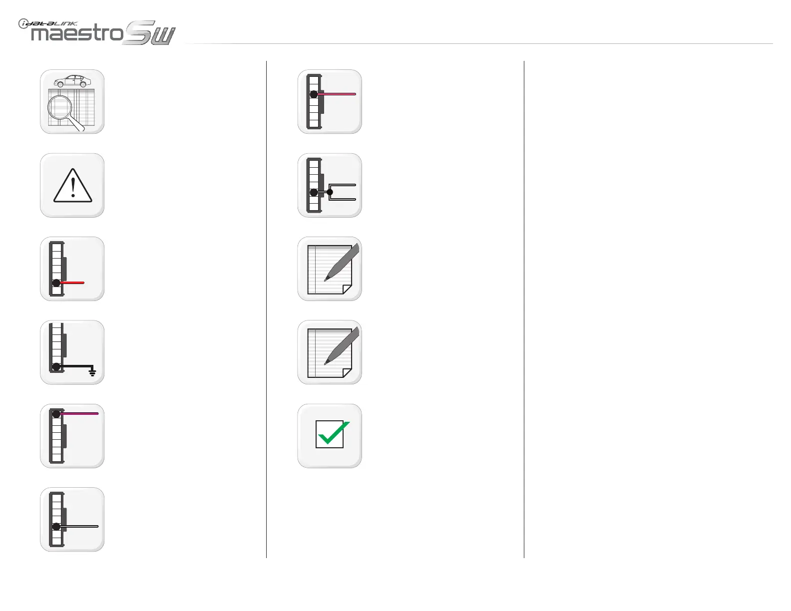
mODulE INsTallaTION PROCEDuRE - 1 Of 1
Refer to WIRE CHART and locate wires.
WARNING: Do not connect module PURPLE/
YELLOW wire (Connector A, Pin 2) nor PINK/
YELLOW wire (Connector A, Pin 4).
Connect module RED wire (Connector A, Pin 6)
to 12V accessory.
Connect module BLACK wire (Connector A,
Pin 7) to ground.
Connect module PURPLE/RED wire (Connec-
tor A, Pin 1) to SWI-1 wire.
Connect module BLACK/WHITE wire (Connec-
tor A, Pin 5) to SWI-F wire. (Disregard this step
if no SWI-F wire is found).
If SWI-2 wire exists, connect module PINK/
RED wire (Connector A, Pin 3) to SWI-2 wire.
If another SWI-F wire exists, connect module
BLACK/WHITE wire (Connector A, Pin 5) to
SWI-F wire.
NOTE: If installing a Kenwood radio, connect
module BLUE/YELLOW wire (Connector C, Pin
1) to remote input (radio BLUE/YELLOW wire).
NOTE: If installing an Aftermarket radio, con-
nect module 3.5mm (1/8”) audio jack (Connec-
tor C, Pin 2, 3 & 4) to auxiliary input.
Module installation procedure completed.
www.maestro.idatalink.comAutomotive Data Solutions Inc. © 2012
ADS-SW(SI)-ALL01-AS-IG-EN
PagE 4 Of 8
• 20120913
DOC.: #9729

 Loading...