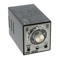
GT3D Series
Timers
817
USA: 800-262-IDEC Canada: 888-317-IDEC
Switches & Pilot Lights Display Lights Relays & Sockets Timers Terminal Blocks
Circuit Breakers
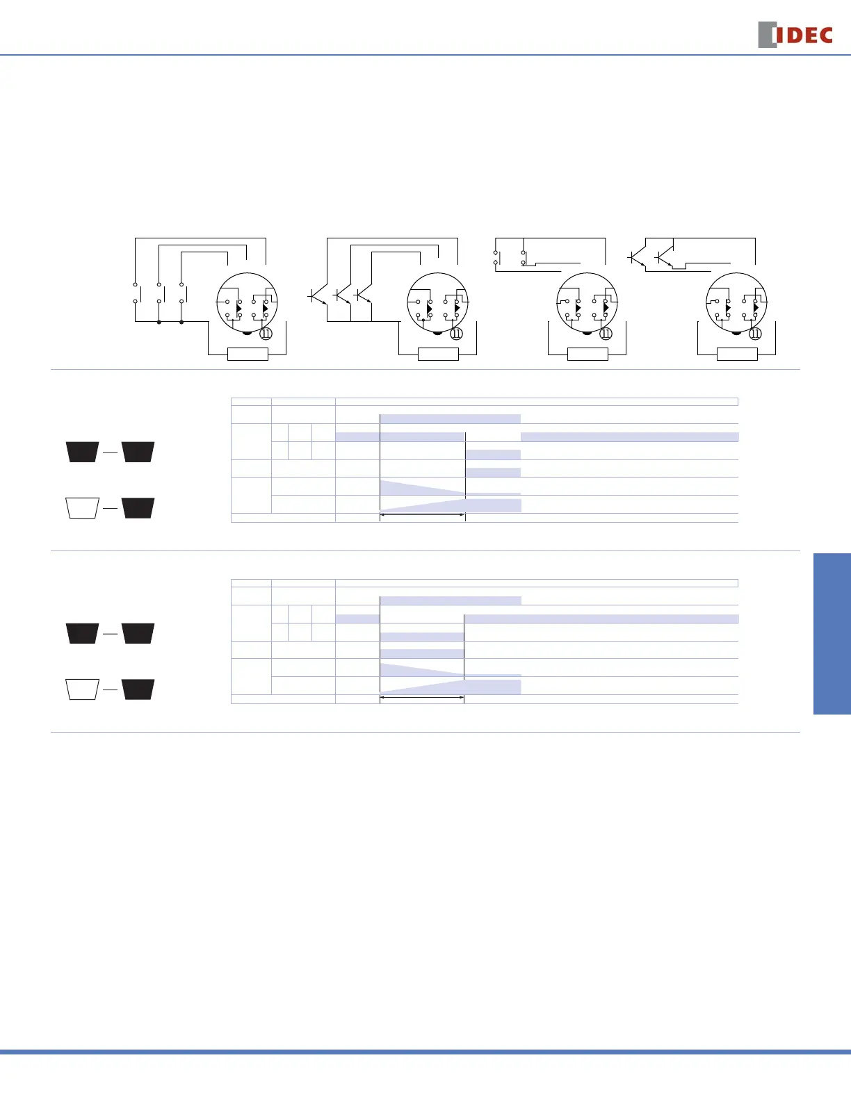
GT3D-4 Timing Diagrams
These timers require a start input. A gate and reset input are optional. Inputs are controlled by external pushbuttons. Reset occurs when the power is removed or
when the reset input is supplied. The gate signal can be used to interrupt (freeze) timer functions. Timer functions resume when the gate input is removed. B style
timers are not equipped for gate input.
Delayed DPDT
Operation
Mode
Selection
(+)(-)
POWER
j
k
l
m
n
o
p
q
r
s
(+)(-)
POWER
j
k
l
m
n
o
p
q
r
s
(+)(-)
(Transistor Input)
(A Type)
(Contact Input)
(B Type)
(Contact Input)
POWER
j
k
l
m
n
o
p
q
r
s
(+)(-)
(Transistor Input)
POWER
j
k
l
m
n
o
p
q
r
s
Reset Start Gate
Reset Start Gate
Start Reset
Start Reset
ON-Delay 1
1
Time Remaining
A
1
Time Elapsed
A
T
Interval 1
1
Time Remaining
B
1
Time Elapsed
B
T
Item Terminal Number Operation
Power 2 - 10
Delayed
Contact
(NC)
1 - 4
8 - 11
8 - 11
(NO)
1 - 3
9 - 11
9 - 11
Indicator OUT
Digital Time
Display
DOWN
UP
Set Time
Item Terminal Number Operation
Power 2 - 10
Delayed
Contact
(NC)
1 - 4
8 - 11
8 - 11
(NO)
1 - 3
9 - 11
9 - 11
Indicator OUT
Digital Time
Display
DOWN
UP
Set Time
Item Terminal Number Operation
Power 2 - 10
Delayed
Contact
(NC)
1 - 4
8 - 11
8 - 11
(NO)
1 - 3
9 - 11
9 - 11
Indicator OUT
Digital Time
Display
DOWN
UP
Set Time
Item Terminal Number Operation
Power 2 - 10
Delayed
Contact
(NC)
1 - 4
8 - 11
8 - 11
(NO)
1 - 3
9 - 11
9 - 11
Indicator OUT
Digital Time
Display
DOWN
UP
Set Time
For information, call 800-221-0487 Switches Unlimited Fax 718-672-6370 www.switchesunlimited.com
tech@switchesunlimited.com sales@switchesunlimited.com
 Loading...