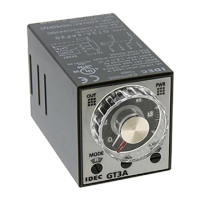
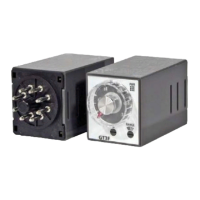
GT3A Series
Timers
806
www.idec.com
Switches & Pilot LightsDisplay LightsRelays & SocketsTimersTerminal Blocks
Circuit Breakers
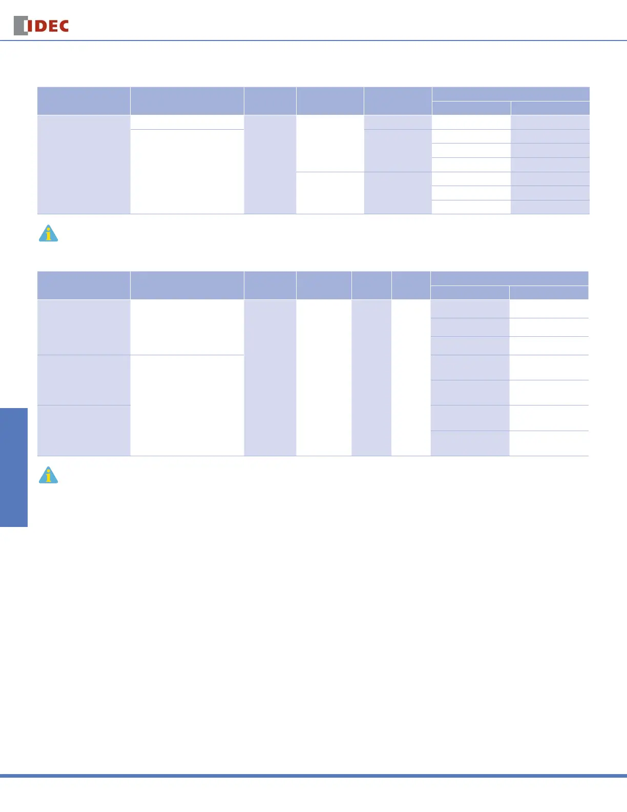
Part Numbers
GT3A-1, -2, -3
Mode Of
Operation
Rated Voltage Code Time Range Output Contact
Complete Part No.
8-Pin 11-Pin
A: ON-delay 1
B: Interval 1
C: Cycle 1
D: Cycle 3
AF20: 100 to 240V AC (50/60Hz)
0.1 seconds
to 180 hours
250V AC, 3A,
30V DC, 1A
(resistive load)
Delayed SPDT GT3A-1AF20 GT3A-1EAF20
AF20: 100 to 240V AC (50/60Hz)
D12: 12V DC
AD24: 24V AC (50/60Hz)/24V DC
Delayed SPDT +
Instantaneous SPDT
GT3A-2AF20 GT3A-2EAF20
GT3A-2D12 GT3A-2ED12
GT3A-2AD24 GT3A-2EAD24
240V AC, 5A,
24V DC, 5A
(resistive load)
Delayed DPDT
GT3A-3AF20 GT3A-3EAF20
GT3A-3D12 GT3A-3ED12
GT3A-3AD24 GT3A-3EAD24
1. For wiring schematics and timing diagrams for GT3A-1, -2, -3, see pages 807 and 808 respectively.
2. For more details about time ranges, see instructions on page 812.
3. For socket and accessory part numbers, see page 838.
GT3A-4, -5, -6
Mode of
Operation
Rated Voltage Code Time Range Output Contact Input
Complete Part No.
A (11-pin) B (11-pin)
A: ON-Delay 2
B: Cycle 2
C: Signal ON/OFF-Delay 1
D: Signal OFF-Delay 1
AF20: 100 to 240V AC (50/60Hz)
D12: 12V DC
AD24: 24V AC (50/60Hz)/24V DC
0.1 seconds
to 180 hours
250V AC, 5A,
24V DC, 5A
(resistive load)
Delayed
DPDT
Start
Reset
Gate
GT3A-4AF20 GT3A-4EAF20
GT3A-4D12 GT3A-4ED12
GT3A-4AD24 GT3A-4EAD24
A: Interval 2
B: One-Shot Cycle
C: Signal ON/OFF-Delay 2
D: Signal OFF-Delay 2
AF20: 100 to 240V AC (50/60Hz)
AD24: 24V AC (50/60Hz)/24V DC
GT3A-5AF20 GT3A-5EAF20
GT3A-5AD24 GT3A-5EAD24
A: One-Shot
B: One-Shot ON-Delay
C: One-Shot 2
D: Signal ON/OFF-Delay 3
GT3A-6AF20 GT3A-6EAF20
GT3A-6AD24 GT3A-6EAD24
4. For wiring schematics and timing diagrams GT3A-4,-5,-6, see pages 809, 810, and 811 respectively.
5. For more details about time ranges, see instructions on page 812.
6. A (11-pin) and B (11-pin) differ in the way inputs are wired.
7. For socket and accessory part numbers, see page 838.
8. For the timing diagrams overview, see page 794.
For information, call 800-221-0487 Switches Unlimited Fax 718-672-6370 www.switchesunlimited.com
tech@switchesunlimited.com sales@switchesunlimited.com
 Loading...