GT3F Series
Timers
827
USA: 800-262-IDEC Canada: 888-317-IDEC
Switches & Pilot Lights Display Lights Relays & Sockets Timers Terminal Blocks
Circuit Breakers
Part Numbering List
GT3F
Mode of
Operation
Rated
Voltage Code
Time Range Output Contact Optional Input
Complete Part Number
8-Pin 11-Pin
Power OFF-delay
AF20: 100 to
240VAC (50/60Hz)
0.1 seconds to
600 seconds
250V AC, 5A,
Delayed SPDT Reset
GT3F-1AF20 GT3F-1EAF20
30V DC, 5A (resistive load) GT3F-1AD24 GT3F-1EAD24
AD24: 24V AC/DC
250V AC, 3A,
Delayed DPDT
None (8p)
Reset (11p)
GT3F-2AF20 GT3F-2EAF20
30V DC, 3A (resistive load) GT3F-2AD24 GT3F-2EAD24
Optional reset input resets the contact to the OFF state before time out.
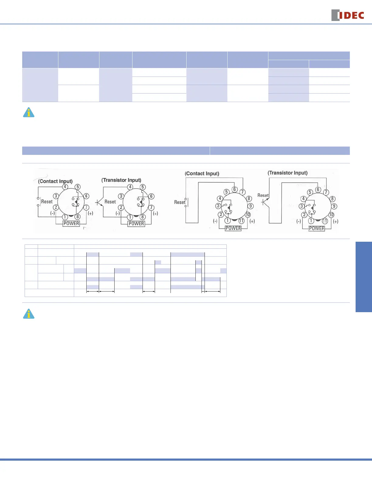
Timing Diagrams/Schematics
GT3F-1 Timing Diagrams
GT3F-1 (8-pin) GT3F-1E (11-pin)
Delayed SPDT Output, with Reset Input
Item Terminal Number Operation
Power
2 - 7 (8p)
2 - 10 (11p)
Reset
Input
1 - 4 (8p)
6 - 7 (11p)
ON or L
Delayed
Contact
5 - 8 (8p)
1 - 4 (11p)
(NC)
6 - 8 (8p)
1 - 3 (11p)
(NO)
Indicator POWER
Set Time
Tr T Ta Ts T
T = Set time
Ta = Shorter than set time
Ts = 1 Second
Tr = Minimum Power Application Time
GT3F-1: 1 Second
1. For time ranges, see page 829.
2. For sockets and accessory part numbers, see page 838.
3. When power is applied, the NO output contact closes. When power is removed, the timing period
begins. When time has elapsed, the NO contact opens.
4. For the timing diagram overview, see page 794.
For information, call 800-221-0487 Switches Unlimited Fax 718-672-6370 www.switchesunlimited.com
tech@switchesunlimited.com sales@switchesunlimited.com
 Loading...