GT3F Series
Timers
830
www.idec.com
Switches & Pilot LightsDisplay LightsRelays & SocketsTimersTerminal Blocks
Circuit Breakers
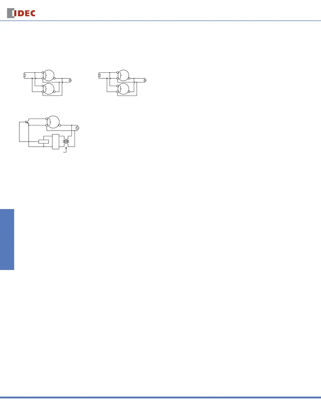
Instructions: Wiring Inputs
Inputs of GT3F
To avoid electric shock, do not touch the input signal terminal during power voltage application.
Never apply the input signals to two or more GT3F timers using the same contact or transistor.
Input
Contact or Transistor
GT3 Series
Timer
Input
Terminal
Input
Terminal
Power
10
10
2
2
[Incorrect]
Power
10
10
2
2
Input
Terminal
Input
Terminal
[correct]
In a transistor circuit for controlling input signals, with its primary and secondary power circuits isolated, do not ground the secondary circuit.
GT3 Series
Timer
Input
Terminal
Power
Rectifier
Circuit
Circuit
Insulating Transformer
On the GT3F timers, connect the input signals to terminal No.1 and 4 only on the 8-pin type; connect the input signals to terminal No. 6 and 7 only on the 11-pin type.
Never apply voltage to other terminals; otherwise, the internal circuit may be damaged.
Input signal lines must be made as short as possible and installed away from power cables and power lines. Use shielded wires or a separate conduit for input wir-
ing.
The GT3F, consisting of a high-impedance circuit, may not be reset due to the infl uence of an inductive voltage or residual voltage caused by a leakage current. If not
reset, connect an RC fi lter or bleeder resistor between power terminals so that the voltage between power terminals can be reduced to less than 15% of the rated
voltage.
For information, call 800-221-0487 Switches Unlimited Fax 718-672-6370 www.switchesunlimited.com
tech@switchesunlimited.com sales@switchesunlimited.com
 Loading...