GT3 Series Instructions
Timers
841
USA: 800-262-IDEC Canada: 888-317-IDEC
Switches & Pilot Lights Display Lights Relays & Sockets Timers Terminal Blocks
Circuit Breakers
Inputs Instructions, continued
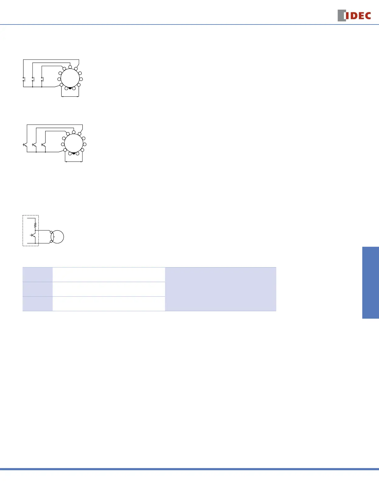
For contact input, use gold-plated contacts to make sure that the residual voltage is less than 1V when the contacts are closed.
6
5
4
3
2
111
10
9
8
7
Power
Reset Input
Start Input
Gate Input
For transistor input, use transistors with the following specifi cations; VCE = 40V, VCES = 1V or less, IC = 50 mA or more, and ICBO = 50μA or less. The resistance
should be less than 1kΩ when the transistor is on. When the output transistor switches on, a signal is input to the timer.
6
5
4
3
2
111
10
9
8
7
Power
Reset Input
Start Input
Gate Input
Inputs: GT3A-1, -2, -3
Transistor output equipment such as proximity switches and photoelectric switches can input signals if they are voltage/current output type, with power voltage
ranges from 18 to 30V and have1V. When the signal voltage switches from H to L, a signal is input to the timer
Transistor
Transistor Output
Circuit
2
5, 6, 7
Input
Terminal
Inputs: GT3A-4, -5, -6
Start Input
The start input initiates a time-delay operation and controls
output status.
No-voltage contact inputs and NPN open collector transis-
tor inputs are applicable.
24V DC, 1mA maximum
Input response time: 50msec maximum
Reset Input
When the reset input is activated, the time is reset, and
contacts return to original state.
Gate Input
The time-delay operation is suspended while the gate input
is on (pause).
For information, call 800-221-0487 Switches Unlimited Fax 718-672-6370 www.switchesunlimited.com
tech@switchesunlimited.com sales@switchesunlimited.com
 Loading...