GT3 Series Instructions
Timers
840
www.idec.com
Switches & Pilot LightsDisplay LightsRelays & SocketsTimersTerminal Blocks
Circuit Breakers
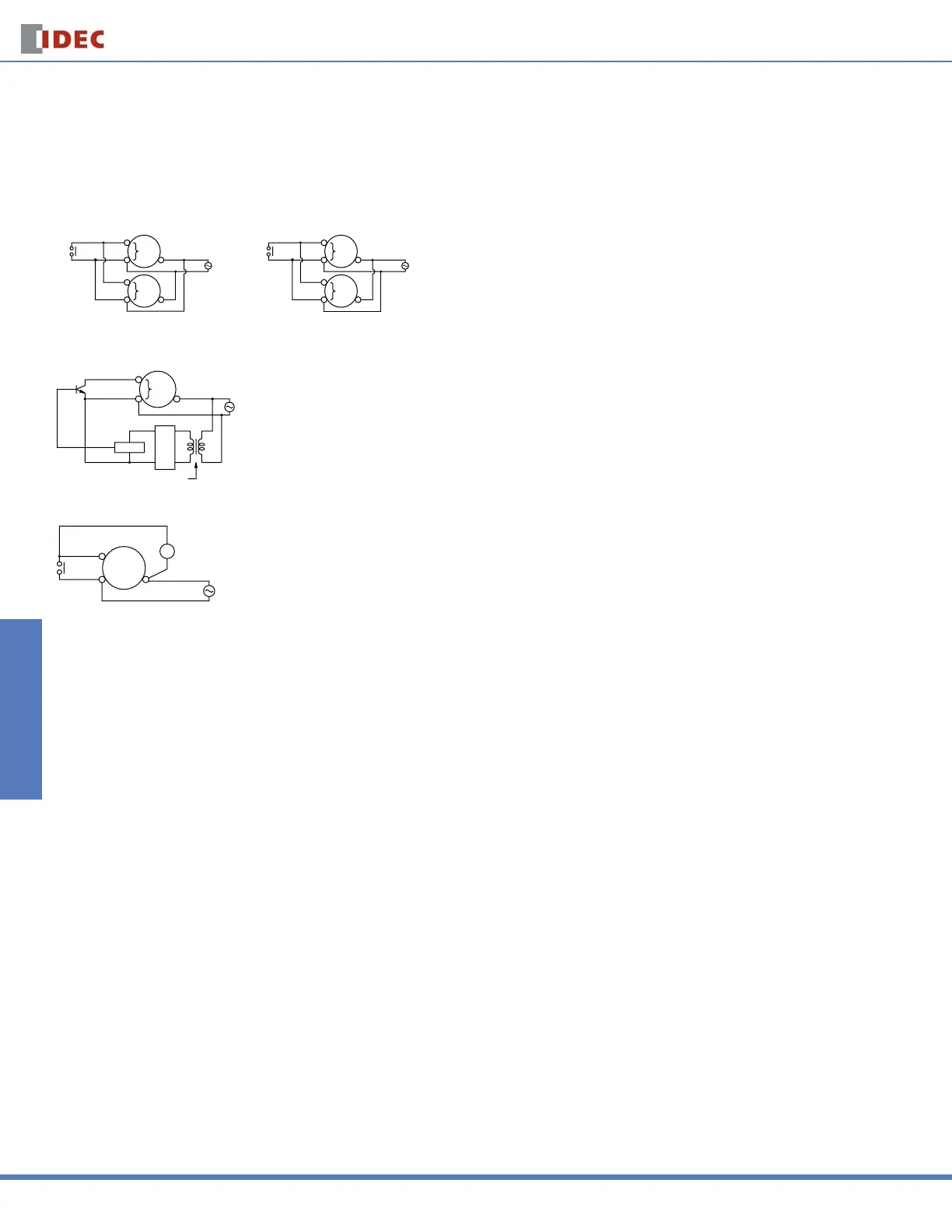
Instructions: Wiring Inputs for GT3 Series
Inputs Inputs
To avoid electric shock, do not touch the input signal terminal during power voltage application.
When connecting the input signal terminals of two or more GT3A timers to the same contact or transistor, the input terminals of the same number should be con-
nected. (Connect Terminals No.2 in common.)
Input
Contact or Transistor
GT3 Series
Timer
Input
Terminal
Input
Terminal
Power
10
10
2
2
[Incorrect]
Power
10
10
2
2
Input
Terminal
Input
Terminal
[correct]
In a transistor circuit for controlling input signals, with its primary and secondary power circuits isolated, do not ground the secondary circuit.
GT3 Series
Timer
Input
Terminal
Power
Rectifier
Circuit
Circuit
Insulating Transformer
Connect the input signal terminals of the GT3A timers to Terminal No.2 only. Never apply voltage to other terminals; otherwise, the internal circuit may be damaged.
Power
R
Y
5, 6, and 7
Input Terminal
210
Input signal lines must be made as short as possible and installed away from power cables and power lines. Use shielded wires or a separate conduit for
input wiring.
Courtesy of Steven Engineering, Inc.-230 Ryan Way, South San Francisco, CA 94080-6370-Main Office: (650) 588-9200-Outside Local Area: (800) 258-9200-www.stevenengineering.com
 Loading...