1.4. Wiring to 805 Interface
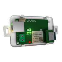
The HYYP unit connects to the IDS 805 Key-bus Interface via a serial cable, the Interface then
connects to the 805 panel via the keypad bus as a second keypad. The LED on the interface
board, will come on when the module has power and has received a valid clock pulse from the
IDS805 alarm panel.
The serial connection between the HYYP Hub and the IDS 805 Key-bus Interface is shown in
the image above.
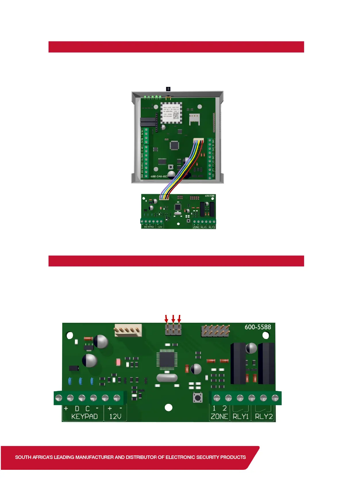
1.5. Interface Board Jumpers
The interface board has 3 jumpers to enable/disable certain hardware.
Jumper 1: Configures what device the interface is connected to. Keep on for HYYP.
Jumper 2: Enables zone 2 on the interface board. (Reports as zone 10 )
Jumper 3: Enables zone 1 on the interface board. (Reports as zone 9 )
 Loading...