Do you have a question about the IEI Technology ICEFIRE2-T10 and is the answer not in the manual?
Provides a general description of the ICEFIRE2-T10 mobile clinic assistant.
Lists the standard features and capabilities of the ICEFIRE2-T10 device.
Details the different available models of the ICEFIRE2-T10 series.
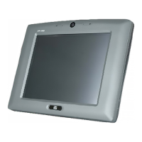
Describes the components and layout of the device's front panel.
Explains the functions of buttons and LED indicators on the front panel.
Details the components and connectors located on the rear panel.
Describes the connectors and buttons present on the side panels.
Details the buttons and controls located on the top panel.
Describes the docking connector and other features on the bottom panel.
Lists the detailed hardware and software specifications of the ICEFIRE2-T10.
Provides the physical dimensions (W x H x D) of the ICEFIRE2-T10.
Step-by-step instructions for safely unpacking the ICEFIRE2-T10.
Lists all the components included in the ICEFIRE2-T10 package.
Instructions for installing and securing the battery packs.
Details on how to charge the battery packs via the device or docking station.
Procedure for installing a SIM card to enable 3G network connectivity.
Lists the frequency ranges supported by the optional WWAN datacard.
Explains options for mounting the ICEFIRE2-T10 system.
Steps to correctly place the ICEFIRE2-T10 onto its docking station.
Instructions for VESA mounting the docking station.
Overview of the device's Input/Output connectors.
Procedure for connecting an Ethernet LAN cable to the device.
Instructions for connecting USB peripherals to the device.
Steps to install and configure the optional smart card reader.
Details the I/O connectors available on the docking station.
How to connect serial devices using the DB-9 connector.
Provides the pinout configuration for the RS-232 serial port.
Instructions for connecting an external VGA monitor.
Step-by-step guide on how to power on the ICEFIRE2-T10 system.
Guide on how to operate and use the integrated RFID reader.
Instructions for operating and utilizing the barcode scanner.
Details on configuring parameters for the barcode scanner.
Lists all software drivers available for installation on the system.
Instructions for installing the Intel chipset driver.
Steps to install the Intel graphics driver for display.
Instructions for installing the Realtek network interface driver.
Guide for installing drivers for the speaker and microphone.
Instructions to install the driver for the barcode scanner.
Steps for installing the fingerprint reader driver.
Instructions for installing the Bluetooth wireless driver.
Steps to install the wireless Local Area Network driver.
Instructions for installing the 3G module driver and watcher program.
Steps for installing the USB 3.0 controller driver.
Instructions for installing the RFID reader driver.
Guide to install the ICEFIRE Control Center software.
How to launch and navigate the ICEFIRE Control Center.
Overview of the capabilities and features of the Control Center.
How to check and manage the status of hardware modules.
Configuration options for the device's built-in cameras.
Steps to calibrate the digitizer and touch screen for accuracy.
Guide on customizing front panel buttons for specific actions.
Assigning a specific application or process to a programmable button.
Mapping Windows key functions to programmable buttons.
Overview of the BIOS setup program and its purpose.
How to access and enter the BIOS setup utility.
Explains navigation keys and basic operations within the BIOS setup.
Information on how to access help screens within the BIOS setup.
Description of the main menu items available in the BIOS setup.
Overview of the Main BIOS menu, displaying basic system information.
Section for configuring advanced system settings.
Configuration options for Advanced Configuration and Power Interface (ACPI).
Settings for configuring real-time clock (RTC) wake events.
Details and configuration for the Central Processing Unit (CPU).
Settings for configuring SATA devices (IDE, AHCI, RAID modes).
Options for configuring USB devices and legacy support.
Configuration settings for the serial ports on the system.
Specific configuration options for the first serial port.
Monitors system hardware parameters like temperature.
Configures console redirection functionality via the serial port.
Configuration settings for the IEI specific features, like One Key Recovery.
Access to Northbridge and Southbridge chipset configuration menus.
Configuration settings for the Northbridge chipset.
Configuration options for the Intel Integrated Graphics Device (IGD).
Configuration settings for the Southbridge chipset.
Configures system boot options, boot order, and NumLock state.
Settings for configuring system and user passwords.
Options to save changes, discard changes, and exit the BIOS setup.
Introduction to component replacement and maintenance procedures.
Essential precautions to prevent damage from electrostatic discharge (ESD).
Instruction to ensure the system is powered off before maintenance.
Guidance on contacting support for motherboard replacement.
Step-by-step instructions for replacing the mSATA module.
Overview of the external peripheral connectors on the motherboard.
Details of internal connectors accessible when the motherboard is removed.
Pinout details for the internal barcode connector.
Pinout details for the internal battery connector.
Pinout details for the internal Bluetooth connector.
Pinout details for the internal button connector.
Pinout details for the rear camera connector.
Pinout details for the front camera connector.
Pinout details for the camera shutter connector.
Pinout details for the internal debug connector.
Pinout details for the digitizer sensor connector.
Pinout details for the internal docking station connector.
Pinout details for the first internal fan connector.
Pinout details for the second internal fan connector.
Pinout details for the internal fingerprint reader connector.
Pinout details for the internal GPS connector.
Pinout details for the internal keyboard connector.
Pinout details for the internal keypad connector.
Pinout details for the internal LED torch connector.
Pinout details for the internal LVDS display connector.
Pinout details for the internal microphone connector.
Pinout details for the internal power input connector.
Pinout details for the internal power button connector.
Pinout details for the internal RFID connector.
Pinout details for the internal speaker connector.
Pinout details for the first internal SPI flash connector.
Pinout details for the second internal SPI flash connector.
Pinout details for the internal touch panel connector.
General safety guidelines and precautions for using the device.
Specific safety measures to be followed during operation and handling.
Detailed procedures to prevent damage from electrostatic discharge (ESD).
Guidelines for the proper disposal of the product and its components.
Precautions to be taken during device maintenance and cleaning.
General advice and procedures for cleaning the ICEFIRE2-T10.
Lists recommended tools and materials for cleaning the device.
Table detailing hazardous substances in product components per China RoHS standards.
| Display Size | 10.1 inches |
|---|---|
| Resolution | 1280 x 800 |
| Touch Technology | Projected Capacitive |
| Processor | Intel Atom x5-Z8350 |
| RAM | 4 GB |
| Storage | 64 GB eMMC |
| Operating System | Windows 10 IoT Enterprise |
| Storage Temperature | -20°C to 60°C |
| Power Supply | 12V DC |
| Weight | 1.2 kg |
| Connectivity | Wi-Fi, Bluetooth |
| Ports | USB 3.0, HDMI, Micro SD slot |
| Operating Temperature | 0°C to 50°C |
| Humidity | 10% to 90% (non-condensing) |