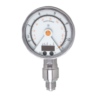
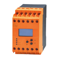
This document describes the PG24xx electronic manometer, a device designed to monitor system pressure in a plant.
Function Description
The PG24xx unit generates two output signals based on parameter settings:
- OUT1: A switching signal for system pressure limit values. This output can be configured for hysteresis function (normally open or normally closed) or window function (normally open or normally closed).
- OUT2: An analogue signal (4...20 mA or 20...4 mA) for the current system pressure. The scaling of this analogue output can be set via a teaching process or by entering specific values for the Analogue Start Point (ASP) and Analogue End Point (AEP) parameters.
The unit displays the current system pressure through an analogue circular scale with a pointer and a 4-digit alphanumeric digital display. Additionally, an LED ring provides various display options, including set point and reset point, trend display (rising/falling pressure), lag indicator for maximum or minimum values, and display of pulsating signals and pressure peaks.
The device also supports customer-specific calibration, allowing the curve of measured values to be adjusted relative to the real measured values (shifting/changing the gradient). Two independent calibration points (CP1, CP2) can be defined within the measuring range. A zero-point calibration (COF) further influences the curve of measured values.
Important Technical Specifications
Pressure Type: Relative pressure.
Measuring Ranges (examples):
- PG2409: -1...1 bar (-14.52...14.52 PSI)
- PG2450: 0...400 bar (0...5800 PSI)
- PG2458: -12.5...250 mbar (-5.0...100.4 inH2O)
Permissible Overpressure: Varies by model, e.g., 10 bar for PG2409, 800 bar for PG2450.
Bursting Pressure: Varies by model, e.g., 30 bar for PG2409, 1200 bar for PG2450.
Note: The indicated bursting pressure must not be exceeded. Exceeding it, even for a short time, can destroy the unit and poses a risk of injury.
Electrical Connection:
- Pin 1: Ub+ (brown)
- Pin 3: Ub- (blue)
- Pin 4 (OUT1): Binary switching output pressure monitoring (black)
- Pin 2 (OUT2): Analogue output for system pressure (white)
- Voltage supply according to EN 50178, SELV, PELV.
- For cULus scope of validity: The sensor must be connected using an R/C (CYJV2) cord with suitable ratings. The device must be supplied from an isolating transformer with a secondary listed fuse rated max 5 amps for 0~20 Vrms or 100/Vp for 20~30 Vrms.
Output Signal Characteristics:
- Analogue Output (OUT2): 4...20 mA or 20...4 mA.
- System pressure above measuring range: 20 to 20.5 mA ([OU2] = [I]) or 4 to 3.8 mA ([OU2] = [InEG]).
- System pressure below measuring range: 4 to 3.8 mA ([OU2] = [I]) or 20 to 20.5 mA ([OU2] = [InEG]).
- Minimum distance between ASP and AEP: 25% of the final value of the measuring range.
- Minimum distance between calibration points CP1 and CP2: 5% of the final value of the measuring range.
- Maximum correction value for calibration: ±2% of the final value of the measuring range.
Damping:
- Switching outputs and display (dAP): 0.01 to 30 s. Influences switching frequency (fmax = 1 ÷ 2dAP).
- Analogue output (dAA): 0.01 to 30 s.
Display Update Rate (diS):
- d1: every 50 ms
- d2: every 200 ms (factory setting)
- d3: every 600 ms
- OFF: Deactivates measured value display in Run mode; touching a button shows value for 15s.
Usage Features
Operating and Display Elements:
- Analogue display: Shows current system pressure in bar, PSI, mbar, or inH2O.
- LED ring: Configurable to display set point/reset point, min/max lag, pulsating signals/pressure peaks, or pressure trend.
- Indicator LEDs: Indicate unit of digital display (bar, mbar, PSI, inH2O), percentage of scaling, or switching status of OUT1.
- Alphanumeric display (4 digits): Shows current system pressure, parameters, and parameter values.
- Touch button Set: Used for setting parameter values (brief touch for step-by-step, permanent touch for continuous change).
- Touch button Mode/Enter: Used for selecting parameters and acknowledging values.
Parameter Setting:
- Parameters are set in a menu structure (main menu and extended functions).
- Changes to COF, CP1, and CP2 take effect immediately; other parameters apply after setting is completed.
- Timeout: If no touch button is activated for 15s during parameter setting, the unit returns to operating mode with unchanged values.
Display Configuration:
- Unit of measurement (Uni): Selectable (bar, mbar, PSI, inH2O) depending on the device.
- Display mode (SELd): Shows pressure in set unit [P] or as percentage of analogue output scaling [P%].
Output Signal Configuration:
- Output functions (OU1, OU2): Select switching function (hysteresis/window, NO/NC) and analogue function (4...20mA / 20...4mA).
- Switching limits (SP1, rP1): Set the value at which OUT1 switches on (SP1) and off (rP1). rP1 must always be lower than SP1.
- Analogue value scaling (tASP, tAEP, ASP, AEP): Can be taught by applying minimum/maximum pressure or by direct value entry.
- Switching logic (P-n): Selectable as pnp or npn.
User Settings (Optional):
- Zero point calibration (COF/tCOF): Shifts the internal measured value "0" by -5% to 5% of the final measuring range value. Can be set automatically by applying no pressure.
- Delay times for OUT1 (dS1, dr1): Set switch-on and switch-off delays between 0.1 and 50s.
- Damping (dAP, dAA): Configures response time for switching outputs/display and analogue output.
- Calibration (CAL, CP1, CP2): Allows for customer-specific calibration of the measured value curve using two calibration points.
Locking/Unlocking:
- The unit can be electronically locked to prevent unintentional operation. A specific sequence of button presses is required to lock or unlock the device.
Maintenance Features
Service Functions:
- Read min/max values (HI, LO): View the maximum and minimum system pressure values recorded.
- Delete memory: Reset the stored min/max values.
Reset to Factory Setting (rES):
- All parameters can be reset to their factory default values. It is recommended to record current settings before performing a reset.
Error Indications:
- [OL]: Overload pressure (measuring range exceeded).
- [UL]: Underload pressure (below measuring range).
- [SC1]: Short circuit in OUT1 (output switched off until short circuit persists).
- [Err]: Flashing indication for internal error or invalid entry.
- These error messages are displayed even if the main display is switched off.
Installation:
- Installation, electrical connection, set-up, operation, and maintenance must be carried out by qualified personnel.
- Ensure no pressure is applied to the system before installing or removing the unit.
- Horizontal installation is recommended for high medium temperatures.
- The unit can be fixed using seals to DIN EN 837-1, sealing tape, or at flange G½ (based on DIN 3852-11).
- After installation, the analogue display can be rotated/adapted to the installation position (wear protective gloves).
General Safety:
- Read the document before setup and keep it for the entire service life.
- Ensure suitability for applications and environmental conditions.
- Use only for intended purpose and permissible media.
- Non-compliance with instructions or technical data can lead to injury or property damage.
- Manufacturer assumes no liability for consequences from tampering or incorrect use.
- Protect units and cables against damage.
- High-pressure units include an integrated damping device for safety against bursting and UL compliance. Removing this device renders the unit unusable and non-compliant with UL conditions.
- Avoid static and dynamic overpressure exceeding overload pressure.
- Use in gases at pressures > 25 bar only after contacting ifm electronic.