Rev. 1.0 Page 22
START
STOP
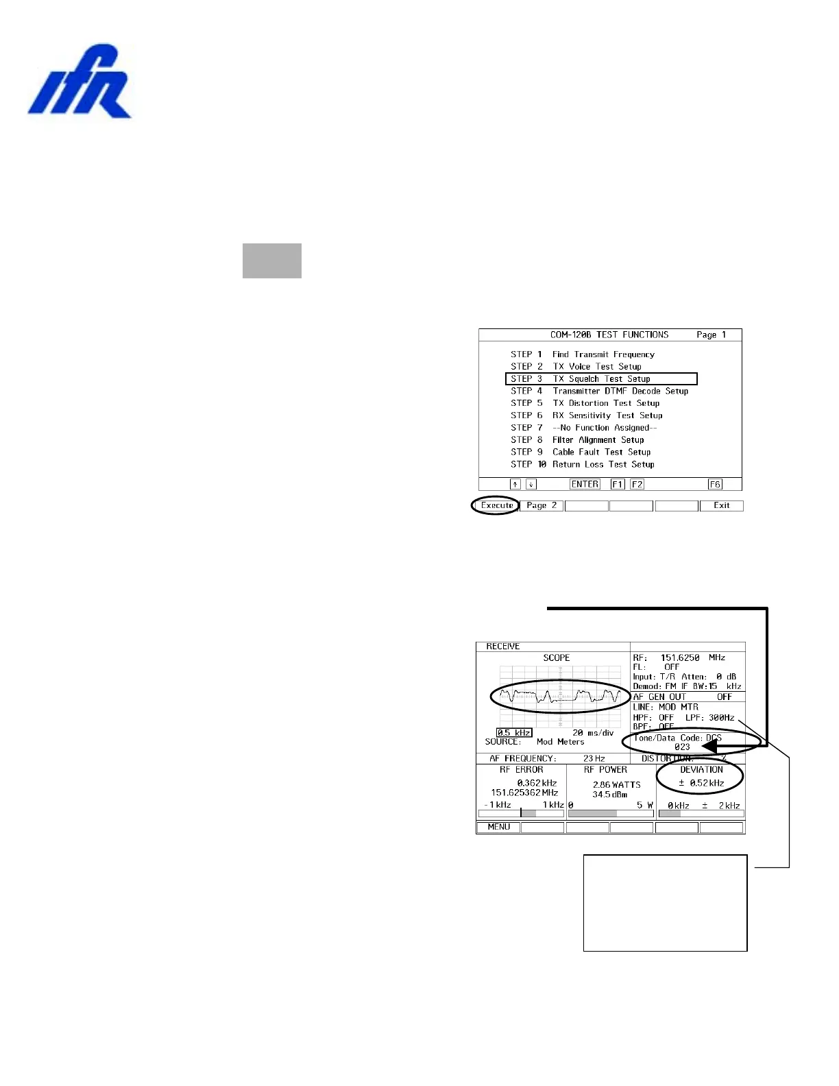
The Modulation meter
and Data Decoder
have been configured
for a 300 Hz Low Pass
filter for this test.
Test TX Squelch (DCS)
Setup:
1. This COM-120B has been pre-configured for common transmitter test
setups.
2. Press the key to access the COM-120B System Setup
Utility software.
3. The menu to the right will appear.
4. Select STEP 3 by positioning the
cursor and pressing F1 Execute.
5. The COM-120B will configure itself
for testing Transmitter Squelch or
SUB Audible deviation.
6. With the radio configured to channel 4, key the radio and observe the
DCS signal on the Scope and on the Deviation meter.
7. The DCS code is decoded and displayed.
8. DCS deviation should be
approximately 500 Hz or 0.5 kHz.
 Loading...