Do you have a question about the IFR FM/AM-500 and is the answer not in the manual?
Overview of the FM/AM-500/A communications service monitors.
Procedures for rescuing shock victims and essential first aid steps.
Precautions for handling ICs and solid-state devices to prevent ESD damage.
Covers the manual's purpose, scope, applicability of terminology, and its overall structure.
Introduces calibration procedures for FM/AM-500A indicators and internal modules.
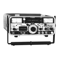
General overview and electrical description of the FM/AM-500A, including front panel controls.
Describes tone generators and RF frequency selection methods.
Explains the dual analog DC milliammeters and their functions.
Details how operating modes and bandwidths are selected.
Provides an introduction to the theory of operation and an overview of modules.
Details open PC boards, enclosed PC boards, and block modules.
Explains the unit's operation as a receiver and generator.
Explains system-oriented theory for functions involving multiple modules.
Provides step-by-step test procedures for assessing FM/AM-500A performance.
Differentiates between quick mobile checks and detailed laboratory procedures.
Details test setup diagrams and initial control settings required for procedures.
Refers to Appendix B for a comprehensive list of required test equipment.
Procedures for evaluating the performance of the 1 kHz and variable tone generators.
Step-by-step instructions and notes for performing test procedures.
Lists required test equipment, setup diagrams, initial controls, and step-by-step instructions.
Lists required equipment, setup diagrams, and initial control settings for receiver testing.
Step-by-step instructions for performing the receiver performance evaluation.
Lists required equipment, setup diagrams, and initial control settings for the RF error meter test.
Step-by-step instructions for performing the RF error meter performance evaluation.
Lists required equipment, setup diagrams, and initial control settings for the audio error meter test.
Step-by-step instructions for performing the audio error meter performance evaluation.
Lists required equipment, setup diagrams, and initial control settings for the generate mode and modulation meter test.
Step-by-step instructions for performing the generate mode and modulation meter evaluation.
Detailed procedure for evaluating the 1 kHz tone generator in a lab setting.
Lists required test equipment, setup diagrams, initial controls, and step-by-step instructions.
Lists required test equipment, setup diagrams, initial controls, and step-by-step instructions.
Lists required equipment, setup diagrams, initial controls, and step-by-step instructions for receiver testing.
Step-by-step instructions for performing the lab test.
Lists required test equipment, setup diagrams, initial controls, and step-by-step instructions.
Lists required equipment, setup diagrams, and initial control settings for the RF error meter test.
Lists required equipment, setup diagrams, and initial control settings for the audio error meter test.
Lists required equipment, setup diagrams, and initial control settings for the modulation and power meter test.
Lists required equipment and procedures for testing SINAD using distortion analyzer or oscilloscope.
Lists required test equipment and procedures for power meter calibration.
Introduces calibration procedures for FM/AM-500A indicators and internal modules.
Lists critical safety precautions to observe during calibration procedures.
Specifies case removal requirements and the recommended order for calibrating interactive modules.
States test equipment needs and identifies controls and calibration points.
Procedure for mechanically zeroing the Modulation and Frequency Error Meters.
Lists prerequisites, required equipment, and calibration steps for the battery charger circuit.
Calibration steps for optional power supply and distributed voltages.
Lists prerequisites, equipment, and coarse calibration steps for the 10 MHz oscillator.
Procedures for fine calibration to WWV and external counter standards.
Lists prerequisites, required equipment, and initial control settings for calibration.
Lists prerequisites, required equipment, and initial control settings for frequency error meter calibration.
Lists prerequisites, required equipment, and test setup diagrams for modulation meter calibration.
Lists prerequisites, equipment, and steps for SINAD calibration using a distortion analyzer.
Procedure for calibrating the SINAD meter using an oscilloscope.
Lists prerequisites, required equipment, and calibration points for the power meter.
Lists prerequisites, required equipment, and initial control settings for output level calibration.
Introduces troubleshooting flowcharts and explains how to use them effectively.
Provides initial checks, visual inspection guidance, and safety precautions.
Lists critical safety precautions and refers to Appendix B for test equipment.
Specifies case removal requirements and provides an index of troubleshooting flowcharts.
Troubleshooting procedure for incorrect power supply output voltages.
Lists required test equipment like Battery Load Simulator and Digital Multimeter.
Troubleshooting steps for low sensitivity at specific frequencies.
Lists required test equipment like Spectrum Analyzer and Signal Generator.
Lists required test equipment like Signal Generator and Oscilloscope.
Troubleshooting steps for incorrect carrier amplitude in the generator.
Lists required test equipment like Digital Multimeter, Spectrum Analyzer, and Signal Generator.
Lists required test equipment like Digital Multimeter and Frequency Counter.
Lists required test equipment like Digital Multimeter.
Troubleshooting steps for when the phase lock indicator light is not functioning correctly.
Troubleshooting steps when the High Loop does not phase lock.
Troubleshooting steps when the Low Loop does not phase lock.
General information on removing and disassembling modules within the FM/AM-500A.
Lists required tools and important precautions before starting disassembly.
An index listing modules with their corresponding disassembly and reassembly page numbers.
Step-by-step procedure for removing the FM/AM-500A case.
Procedures for removing the Frequency Standard and Power Supply PC Boards.
Procedure for removing the Audio PC Boards.
Procedures for removing and disassembling enclosed modules.
Procedures for removing and disassembling the Output Amplifier for later serial numbers.
Procedures for removing and disassembling the IF Module.
Procedures for removing and disassembling the Dual VCO module, with caution about realignment.
Procedure for removing the Rear Panel assembly.
Procedure for removing the Front Panel assembly.
Procedure for removing the optional Generate Amplifier.
Procedure for positioning and installing the RF Level Attenuator.
Provides detailed testing procedures for modules to determine if faulty.
Identifies modules that are not field repairable and must be returned to the factory.
States that case and module removal are usually required for testing.
Refers to Appendix B for a list of suitable test equipment.
Lists critical safety precautions for troubleshooting live circuits.
An index listing modules with their corresponding testing procedure page numbers.
Explains the theory of operation for the Power Supply unit.
Details the general, voltage supply, battery charger, and transformer driver circuits.
Instructions for preparing the unit for power supply testing.
Lists required test equipment and details preparation steps including initial switch settings.
Step-by-step testing procedures for the power supply.
Explains the theory of operation for the IF Module in Generate and Receive modes.
Describes RF signal path, static protect, mixer, and filter circuits.
Details mixer/amplifier circuits, VCO circuits, and preparation for testing.
Lists test equipment and details preparation steps including connecting test equipment.
Explains the theory of operation for the Dual VCO module.
Describes the Dual VCO's general function and its first and second VCO circuits.
Details buffer amplifier circuits and the programmable divider network.
Preparation instructions for testing the Dual VCO module.
Testing procedures for the first VCO.
Testing procedures for the second VCO.
Testing procedures for the mixer output.
Explains the theory of operation for the High Loop Synthesizer.
Describes the High Loop's general function and its analog/divider circuits.
Instructions for removing and disassembling the High Loop Synthesizer for testing.
Lists test equipment and details preparation steps including connecting test equipment.
Explains the theory of operation for the Low Loop Synthesizer.
Describes the Low Loop's general function and its VCO, buffer, and divider circuits.
Instructions for removing and disassembling the Low Loop Synthesizer for testing.
Lists test equipment and details preparation steps including connecting test equipment.
Explains the theory of operation for the Receiver/Generator module.
Describes operation in Generate and Receive modes and signal paths.
Details bandpass filters and amplifier circuits for received signals.
Details AM/FM demodulator circuits and the 21.4 MHz VCO.
Details AM modulator, mode power control, and phase lock indicator logic.
Explains the theory of operation for the Digital Module.
Describes the frequency divider, timing, and counter system circuits.
Details the timing and signal selector circuits.
Details the counter system, including latches, DAC, and error detection.
Lists required test equipment and details preparation steps including control settings.
Instructions for reassembling the Digital Module after testing.
Explains the theory of operation for the Receive Audio Module.
Describes how demodulated audio signals are processed and routed.
Explains the audio AGC circuit and lowpass filters.
Details audio AGC, SINAD, and distortion circuits.
Lists required test equipment and details preparation steps including control settings.
Instructions for reassembling the Receive Audio PC Board.
Explains the theory of operation for the Generate Audio Module.
Describes the module's function in processing audio signals and signal switching.
Details signal switching, AM modulator/leveler, and mode power control circuits.
Describes the logic controlling the phase lock indicator LED.
Lists test equipment and outlines preparation steps.
Instructions for reassembling the Generator Audio PC Board.
Explains the theory of operation for the Output Amplifier module for specific serial numbers.
Describes the module's function in amplifying and attenuating RF signals.
Details level detector, receive enable, and power detector circuits.
Describes operation in Receive and Generate modes, including signal path and amplification.
Explains the theory of operation for the Variable Tone Generator.
Describes the module's components like crystal oscillator, ROM/DAC, and adder system.
Explains the adder system using chained adders and thumbwheel inputs.
Details audio signal generation, lowpass filters, and frequency selection detectors.
Lists test equipment and details preparation steps including connecting test equipment.
Instructions for reassembling the Variable Tone Generator.
Explains the theory of operation for the optional Generate Amplifier accessory.
Describes the accessory's function in boosting output signal and its circuit components.
Routine maintenance instructions for cleaning and inspecting the FM/AM-500A.
Procedures for cleaning external and internal parts of the unit.
Guidelines for visually inspecting the chassis, capacitors, connectors, and components.
Explains that this section contains component layout drawings for all PC Boards.
An index listing PC Board assembly drawings alphabetically.
Explains that this section contains module interconnect drawings and circuit schematics.
An index listing circuit schematics by module title, figure, and page.
Lists detailed specifications for the FM/AM-500A.
Provides specifications for the RF signal generator functions.
Lists specifications for audio generator, optional generate amplifier, and receiver/monitor functions.
Provides specifications for master oscillator, frequency error meter, modulation meter, and SINAD/distortion meter.
States that this appendix lists suitable test equipment for maintenance procedures.
Lists recommended test equipment with manufacturer, model, and specifications.
Provides circuit schematic and diagram for the Battery Load Simulator.
Describes the material and fabrication of an attenuator knob spacer.
States that the following defines common abbreviations and symbols used in the manual.
Provides conditions for returning test sets for service or repair, including contact information.
Step-by-step procedure for repackaging the test set for shipping.
| Resolution | 1 Hz |
|---|---|
| Frequency Accuracy | ±1 ppm |
| Modulation Types | FM, AM |
| Display Type | LCD |
| Power Supply | 50/60 Hz |