Rev. 1.0 Page 36
START
STOP
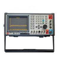
Measuring Filters
Interconnect:
1. Connect an RF cable to the COM-120B’s AUX RF Output.
2. Connect an RF cable to the COM-120B’s Antenna Input.
3. Using a BNC Barrel, connect the two RF cables together forming a
loop with two cables from the AUX RF Output to the Antenna Input of
the COM-120B. This will configure the COM-120B to zero out test
cables for making insertion loss measurements.
Setup:
1. This COM-120B has been pre-configured for common Analyzer test
setups.
2. Press the key to access the COM-120B System Setup
Utility software.
3. The menu to the right will appear.
4. Select STEP 8 by positioning the
cursor and pressing F1 Execute.
5. The COM-120B will configure itself
for filter measurements.
1
2
 Loading...