Rev. 1.0 Page 38
1. Connect the Duplexer Antenna port to the COM-120B’s AUX RF
Output.
2. Connect the Duplexer 160 MHz port to the COM-120B’s Antenna
port.
3. Connect a 50-ohm Termination to the remaining port.
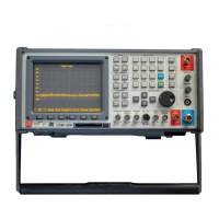
If the filter is properly aligned, the
image to the right will be displayed.
The left side shows the pass band
while the right side shows the reject
band. With the current setup,
examine the left side for insertion
loss. This can be measured from
the top line to where the trace is on
the display. The object is to have
minimum insertion loss here.
TX RX
1
2
3
Alignment screws.
To adjust, loosen the nut and then
turn the screw
Spectrum
Anal
zer #1
Spectrum
Anal
zer #2
 Loading...