23
El montaje y ajuste son efectuados como sique:
- la espiga de bloqueo (321/1) de atoranillarse en
el soporte (321/4
- la tuerca (321/6) se junta con la pieza de conexión
(322) atornillándola
- en el otro lado (pulsador de presión 320), la pieza
no. (321/10) tiene que ser fijada en el agujero del
medio de la palanca (320/10)
- el cable Bowden (321/9) tiene que ser empujado
a través del soporte con rosca interior en la parte
superior de la caja (320/8) y más adelante a través
del taladro de la pieza hexagonal (320/10)
- la espigaguía de protección (321/8) se atornilla
en el soporte de la tapa de la caja (320/8), contra
atornillado la tuerca de fijación (321/11) a mano
- ahora se tira a mano el cable Bowden (321/9) a
través de la pieza afianzadora (321/10) y se fija
apretando el tornillo de (321/109). Finalmente, la
tuerca hexagonal (321/11) debe fijarse
- controlar si la palanca (320/109), al empujarla
hacia la izquierda, todavia tiene juego
Ahora arrancar el aparato y dejar calentarlo.
Después
- volver a controlar la palanca si tiene juego cuando
se empuja a la izguierda, reajustar si es necesario,
¡apretar bien la tuerca hexagonal y tornillo en
(321/10)!
The mounting and the adjustment will be
effected as follows:
- The locking pin (321/1) has to be screwed into
the support (321/4),
- the nut (321/6) has to be screwed on (322),
- on the other side, at the pressure sensitive switch
(320), the screw nipple (321/10), has to be fixed
within the centre hole of the lever (320/10).
- The Bowden cable (321/9) has to be pushed
through the support with internal screw thread to
the housing (320/8) and further through the center
hole of the hexagone part of screw nipple (321/10).
- The protective guard with the end piece (321/8)
has to be screwed into the fixing device of the
housing cover (320/8), the fixing nut (321/11) has
to be fixed by hand.
- Now, the Bowden cable (321/9) has to be pulled
through the clamping part (321/10) and has to
be fixed by tightening the screw of screw nipple
(321/10). Finally the counter nut (321/11) has to
be fixed,
- check if lever (320/10) still has slack when pushing
it to the left.
Now start the unit and let it warm up then
- repeat the lever test to the left (slack) and tighten
the screw (321/10)!
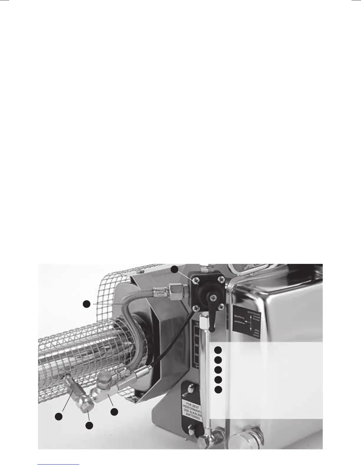
Illus. 6 / illus. 6
1
2
3
4
5
1
llave de agente activo / Solution tap
2
agente activo / Solution line
3
píton nebulizador / Fog solution socket
4
boquilla dosificadora / Dosage nozzle
5
pieza de conexión cable Bowden
con pasador de bloqueo /
Connecting piece Bowden wire
with locking pin