Do you have a question about the IKEA ALEX DRAWER UNIT/CASTERS and is the answer not in the manual?
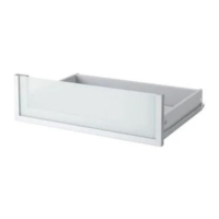
Diagram illustrating the insertion of a component into the main unit.
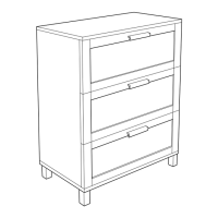
Diagram showing drawer removal with a close-up of screw attachment.
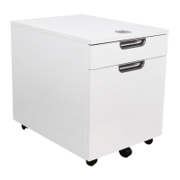
Illustration of the assembled unit with a drawer being accessed.
Diagram for assembling the base panel using screws.
Illustration showing attachment of side panels with screws.
Diagram showing the integration of the back panel.
Illustration of frame reinforcement with screws and dowels.
Diagram showing a curved piece being fitted into a frame.
Illustration of connecting frame parts using screws.
Diagram showing the assembly of side frames using screws.
Illustration of attaching an outer panel to the assembled frame.
Diagram showing the attachment of the top panel with screws.
Illustration of installing drawer slides onto the unit frame.
Diagram showing the assembly of a drawer box with screws.
Illustration of attaching caster wheels to the unit base.
Diagram showing the assembly of support rails with screws.
Illustration of assembling vertical support pieces with screws.
| Product Name | ALEX Drawer Unit/ Casters |
|---|---|
| Category | Indoor Furnishing |
| Brand | IKEA |
| Width | 36 cm |
| Depth | 58 cm |
| Number of Drawers | 5 |
| Color | White |
| Casters Included | Yes |
| Assembly Required | Yes |
| Material | Particleboard, Fiberboard |
| Weight Capacity | 25 kg |