EasyManua.ls Logo

Ikegami CCU-890 - User Manual

Ikegami CCU-890
132 pages
Print Icon
To Next Page IconTo Next Page
Loading...
Products conforming to RoHS directive
Cam era Control Unit
CCU-890
OPERATION MANUAL

Table of Contents

Questions and Answers

  • V
    vanessadouglasAug 1, 2025
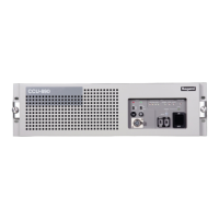
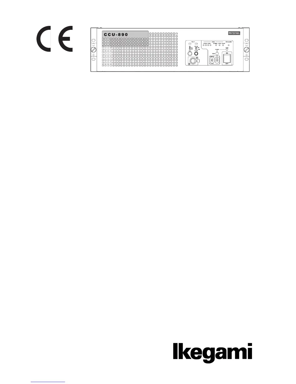
    What to do if the FAN ALARM indicator lights up on my Ikegami CCU-890?
    • M
      Mrs. Christina SmithAug 1, 2025
      If the FAN ALARM indicator is lit, it means one of the three fans inside the CCU has stopped working. Check the fans to ensure they are functioning correctly. If a fan is not working or has reached the end of its lifespan, replace it with a new one.
  • S
    Stacy IbarraAug 8, 2025
    Why is the (CABLE) SHORT indicator lighting up on my Ikegami CCU-890?
    • A
      Alicia McmahonAug 8, 2025
      The (CABLE) SHORT indicator lights when there is a short circuit in the camera cable or the optical connector, possibly due to moisture. Inspect the camera cable for any short circuits and ensure the optical connector is dry. If the connector is wet, dry it thoroughly and then clean it.
  • M
    Mary HernandezAug 15, 2025
    What to do if the (CABLE) OPEN indicator lights up on my Ikegami CCU-890 Camera Accessories?
    • V
      Vanessa RiveraAug 15, 2025
      Check that the camera cable is properly connected and undamaged. If there is an open circuit, replace the camera cable with a new one.
  • M
    Maria WalkerAug 23, 2025
    How to fix Ikegami Camera Accessories when OPTICAL LEVEL indicator lights?
    • S
      shawnschmidtAug 23, 2025
      The OPTICAL LEVEL indicator light changes if the optical connector is dirty. Clean the optical connector.

Summary

SAFETY PRECAUTIONS

Hazard Alert Symbols and Meanings

Explains hazard alert symbols indicating the level of impact on body or property.

Handling Precautions

Details precautions for using the product safely, including warnings and cautions.

Chapter 1 OUTLINE

1.1 Features of This Product

Describes the key functions and capabilities of the CCU-890.

1.2 Specifications

Lists the technical specifications and performance ratings of the CCU-890.

Chapter 2 NAME and FUNCTION

2.1 CCU-890 Front View

Identifies and explains the components and indicators on the front panel.

2.2 CCU-890 Rear View

Identifies and explains the connectors and modules on the rear panel.

Chapter 3 FORMATS and GENLOCK

3.1 HDTV Format

Explains the HDTV formats supported by the CCU-890.

3.2 GENLOCK System

Details input/output connectors and connection examples for the GENLOCK system.

Chapter 4 EQUIPMENT CONNECTIONS

4.1 Preparation & Power Supply

Covers environment setup and procedures for connecting power.

4.3 CCU and Camera Head Connection

Explains how to connect the CCU-890 to the camera head via camera cable.

4.6 External Connections

Details various external connectors for the CCU-890.

Chapter 5 CCU SETTINGS and ADJUSTMENT

5.1 Settings from the CCU Menu

Guides on operating the CCU menu for various settings and adjustments.

5.2 Settings Using Switches on the Module

Explains how to configure functions using DIP switches on modules.

Chapter 6 TROUBLE SHOOTING and MAINTENANCE

6.1 Indicator on the Front of CCU Lights

Troubleshooting guide based on the status of indicator lights on the CCU.

6.2 ALARM Indicator on the Control Panel Flashes ON and OFF

Explains ALARM indicator behavior and self-diagnostic information.

6.3 Replacing Fuses

Provides instructions for replacing blown fuses in the CCU.

Ikegami CCU-890 Specifications

General IconGeneral
TypeCamera Control Unit
CompatibilityIkegami cameras
Video InputsHD-SDI
Video OutputsHD-SDI
Audio InputsXLR
Audio OutputsXLR
Power SupplyAC 100-240V, 50/60Hz
ConnectorsBNC, XLR