Do you have a question about the IKONIX SCI 297 and is the answer not in the manual?
Lists safety and EMC standards the product complies with.
Details compliance with EU directives and RoHS substances.
Covers defects, calibration, unauthorized modifications, and parts.
Reviews safety markings, instructions, and power verification.
Explains symbols and text for warnings and cautions.
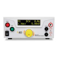
Details each button, knob, and display on the front panel.
Details connectors, ports, and the calibration enable key.
Describes buttons, display, and ports on Model 298 front panel.
Details connectors and ports on Model 298 rear panel.
Step-by-step guide for powering on the tester and initial checks.
Explains the 5 memory programs for storing test settings.
Describes the display parameters during a test.
Guides on setting up test parameters in memory locations.
Instructions to navigate back to the main menu from settings.
Steps to select ACW, DCW, or IR as the test type.
Steps to set the desired voltage for AC Hipot tests.
Setting the upper current limit for AC Hipot tests.
Setting the lower current limit for AC Hipot tests.
Setting the time for voltage to rise to the test level.
Setting the duration the voltage is held at the test level.
Configuring continuity test parameters (ON/OFF).
Explains manual and auto modes for test execution.
Selecting the AC test frequency (50Hz or 60Hz).
Configuring the connection setting for the test.
Selecting DCW as the test type.
Setting the desired voltage for DC Hipot tests.
Setting the upper current limit for DC Hipot tests.
Setting the lower current limit for DC Hipot tests.
Setting the voltage ramp time for DC tests.
Setting the dwell time for DC tests.
Configuring continuity test parameters for DC.
Selecting IR as the test type.
Setting the voltage for Insulation Resistance tests.
Setting the upper resistance limit for IR tests.
Setting the lower resistance limit for IR tests.
Setting the ramp time for IR tests.
Setting the delay time for IR tests.
Configuring the connection setting for IR tests.
Configuring remote test initiation via PLC.
Setting up dual test functionality.
Managing security levels (OFF, RUN, MEM) for the tester.
Step-by-step guide to changing security settings and PIN.
Configuring the PLC Remote ON/OFF parameter.
Setting up the Dual Test parameter (ON/OFF).
Explains various indicators shown during test execution.
Describes indicators for different test failure conditions.
Details failure indicators and their meanings.
Lists and explains common error messages displayed by the tester.
How to check results from sequential tests.
Introduction to remote control and data connectors.
Describes PASS, FAIL, and PROCESSING relay outputs.
Explains TEST, RESET, and INTERLOCK input signals.
Guide for connecting test leads for exposed and non-exposed chassis.
Instructions for connecting the optional adapter box.
Procedures for receiving and checking the tester.
Guidelines for safely handling the tester to prevent injury.
Lists all items included in the tester's packaging.
Specifies voltage, frequency, and fuse requirements.
Guidelines for connecting the power cord safely.
Details temperature, humidity, and altitude limits.
Specifies limits for storing and shipping the tester.
Steps for preparing the tester for return or shipping.
Requirements for personnel operating the tester.
Essential safety practices and rules for testing.
Guidelines on clothing and medical conditions for operators.
Specific safety warnings and precautions during testing.
Guidelines for selecting and marking a safe test area.
Ensuring proper power connection and grounding.
Maintaining a safe, clear, and organized work environment.
Details voltage, frequency, and fuse ratings.
Covers output rating, voltage, and current settings/display.
Specifies high current limits for AC and DC modes.
Specifies low current limits for AC and DC modes.
Covers ripple, capacitive load, waveform, frequency, regulation, dwell, ramp.
Details specifications for continuity and IR tests.
Details resistance display, limits, ramp, and delay timers.
Covers safety listings, remote control, memory, security, and physical specs.
Notes on factory calibration and NIST traceability.
Lists available factory-installed options with codes.
Provides rear panel output connections.
Enables PC communication via USB.
Expands memory locations to ten.
Specifications for 3mA AC current limits and measurement.
Specifications for 3mA DC current limits and measurement.
Enables repeated testing upon failure for Model 295.
Allows holding the TEST button to run tests continuously.
Information on USB interface setup and driver.
Lists commands for controlling the tester via USB.
Commands for controlling output voltage and current.
Commands for creating/modifying test setups in memory.
Lists parameters for ACW, DCW, and IR test types.
Commands to edit voltage, limits, ramp, dwell, etc.
Commands to modify PLC Remote and Security settings.
Commands to retrieve test data, results, and hardware info.
Standard commands for tester identification and control.
Commands like *RST, *TST?, *CLS for tester operation.
Querying status bits like Operation Complete, Errors.
Enabling specific status bits for reporting.
Reading and configuring the Status Byte for requests.
Lists part numbers for accessories like leads, fuses, connectors.
Lists part numbers for panel parts and circuit boards.
Guidelines for safe cleaning and avoiding internal access.
Recommendations for calibration and warnings against modifications.
Lists necessary equipment for calibration.
Steps to enter calibration mode.
Procedure to calibrate AC voltage measurement.
Procedure to calibrate DC voltage measurement.
Procedure to calibrate AC current measurement.
Procedure to calibrate DC current measurement.
Continuation of AC current calibration steps.
Continuation of DC current calibration steps.
Procedure to calibrate continuity offset.
Procedure to calibrate continuity with a 1Ω resistor.
Steps to exit calibration and return to test mode.
| Brand | IKONIX |
|---|---|
| Model | SCI 297 |
| Category | Test Equipment |
| Language | English |