User’s Manual ESC 2051
Copyright © 2004 ILLKO, s.r.o.
33
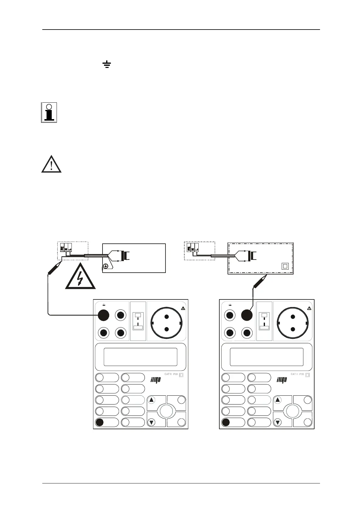
Step 2
• Disconnect protective conductor of tested equipment from its terminal board and
connect it to terminal by means of test lead P 2011 with test tip P 3011 (Fig. 11).
• Make sure, that equipment under test it not connected to potential of ground - for
example with conductive water mine, metallic fixture etc. If equipment under test has
electrical potential equalization connection, disconnect it.
Measurement result can be unfavourably affected by capacitance between equipment
under test and conductive grounded base (e.g. other equipment or grounded fixture).
If there is no possibility to insulate equipment under test (e.g. to place it to a bench
made of insulating material), it is necessary to put at least 50 ÷ 100 mm thick
insulating material under equipment under test to eliminate unwanted capacitance.
WARNING - DANGER!
• Tested equipment starts to run after its main switch is switched on in following
Step! Take into consideration all safety warnings, referred to equipment under
test!
• Do not touch exposed conductive parts of tested object after main switch is
switched on!
Step 3
• Switch on main switch of equipment under test.
SONDE
STA RT
9
7
5
ENTER
DEL
CAL
ESC
1
0
2
3
4
6
8
R
U/R
200mA
∆
10A
R
P
ISO
VA
SAVE
I
LEAK
I
PE
I
PE INV.
PE
PE
I
DIFF.
DEL
I
LOAD
MENU
R
TEMP.
PE
RI
ISO
LEAK
/
STA RT
DEL
CAL
ESC
1
0
2
3
4
6
8
R
U/R
∆
10A
R
P
ISO
VA
SAVE
I
LEAK
I
PE
I
PE
PE
I
DIFF.
DEL
I
LOAD
MENU
PE
RI
ISO
LEAK
/
Fig. 11


 To Next Page