This document is an instruction manual for an ILVE Cooker Hood, specifically models FR60 and FR90. It provides essential information regarding the installation, operation, and maintenance of the appliance.
Function Description:
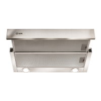
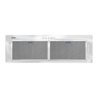
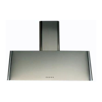
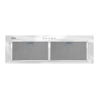
The ILVE Cooker Hood is designed to extract fumes and odors from the kitchen, improving air quality and preventing grease buildup. It can be configured for either ducted or recirculating operation, offering flexibility based on kitchen layout and ventilation requirements. In ducted mode, the extracted air is expelled outside the building, while in recirculating mode, the air is filtered and then returned to the room. The hood features a telescopic board that can be pulled out to activate the fan and lights, and pushed back in when not in use.
Important Technical Specifications:
- Model: FR60/FR90
- Voltage: 220~240V
- Frequency: 50Hz
- Power: 42W
- Ducting Adaptor: 120mm to 125mm
- Minimum Duct Diameter: 125mm
- Recommended Installation Height: No less than 650mm and no more than 750mm above the stove's heating elements and burners.
- Maximum Ducting Length (without in-line motor): 5 meters
- In-line Motor Requirement: For ducting exceeding 5 meters, a TD500 or TD350 in-line motor is required, placed one meter from the external vent.
Usage Features:
- Operation Modes: The hood supports both ducted and recirculating modes. For recirculating mode, a 40mm rail is used, and a tape over the vent in the front of the unit must be removed.
- Controls: The hood is operated by pulling out the telescopic board. It includes a lamp switch (located on the left side) and a fan switch (located on the right side).
- Fan Speed Settings: The fan has three settings: off, low speed, and high speed.
- Lighting: The hood is equipped with a lamp to illuminate the cooking area.
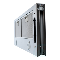
- Telescopic Board: The pull-out telescopic board activates the hood's functions.
- Filler Pieces: Two small filler pieces are provided to fill the gap between the hood and the cupboard during installation.
Maintenance Features:
- Lamp Replacement:
- Switch off the hood and remove the plug.
- Pull out the telescopic board.
- Take off the lamp and remove the connection unit.
- Replace the lamp by turning it in a clockwise direction.
- Fit the connection unit.
- Lamps must be replaced by the manufacturer, its service agent, or similarly qualified persons to avoid hazards.
- Cleaning: The manual emphasizes that cleaning must be carried out in accordance with instructions to avoid fire risk.
- Filter: The hood includes a filter (item 8 in the "Know your cooker hood" diagram) which likely requires regular cleaning or replacement, though specific instructions for filter maintenance are not detailed on the provided pages.
- Electrical Safety: Always check the voltage and frequency on the rating plate inside the hood. Ensure the power is turned off before beginning installation. Do not touch the light bulb within half an hour after appliance use.
- Ducting:
- The air must not be discharged into a flue used for exhausting fumes from other gas or fuel-burning appliances.
- If using a duct, push out the duct hole and fix the damper flap on the air outlet.
- Flexible ducting is discouraged due to its negative impact on airflow and noise; semi-rigid or rigid ducting is recommended.
- Avoid using a narrower duct than specified (minimum 125mm diameter).
- A short duct with minimal bends provides the best performance.
- For vertical flues, if an attic space is available, ducting can run through the cupboard and attic to a roof cap.
- Installation Clearance: The required clearance between the cooktop and the range hood should be determined by consulting both the range hood and cooktop installation manuals. The greater of the two specified distances must be observed, with a minimum of 600mm between the highest point of the highest burner for gas cooktops.
- Mounting: When drilling into walls or ceilings, take care not to damage electrical wiring or other hidden utilities. The hood is fixed using self-tapping screws through the middle four holes on the top board inside the hoods.
- User Supervision: The appliance is not intended for use by young children or infirm persons unless adequately supervised by a responsible person. Young children should be supervised to ensure they do not play with the appliance.
- Manufacturer Responsibility: The manufacturer declines all responsibility if installation, maintenance, and usage recommendations are not observed and respected.