IMER INTERNATIONAL S.p.A.
H110VF - H110VR
31
8.1. Cutting wedges
To cut wedge shapes, use the workpiece guide square as
shown in Þ gure 8-A.
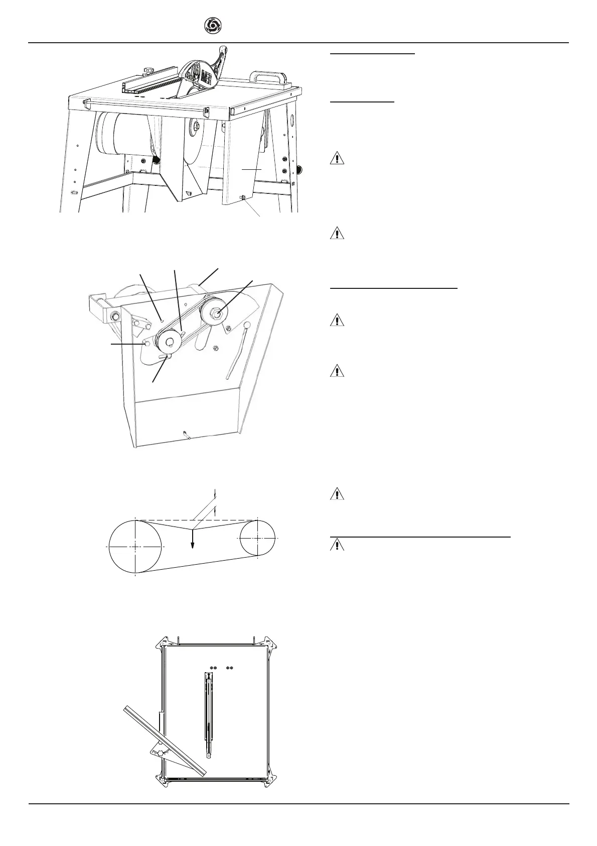
9. Lower guard
The part of the blade that projects below the table is protect-
ed by a steel guard, which has the dual function of prevent-
ing contact with the tool and drive components, and acting
as a chip extractor.
This cover must be removed with the machine stopped
and disconnected from the electrical power supply, through
a simple control: 1) undo the bolt [S] (Þ g.7); 2) remove the
guard [T] (Þ g.7) by pulling it horizontally towards you.
With the guard removed, it is possible to replace the cutting
disc and the drive belts.
On completion of these operations, reÞ t the guard [T]
(Þ g.7) in its original position and secure it with the bolt [S]
(Þ g.7).
10. Replacing the cutting disc
The sawing machine was designed for use exclusively with
cutting discs with the speciÞ cations set out in Table 1.
The choice and state of maintenance of the blades affect
the level of noise to which the operator is exposed.
Use the original IMER spare part, which can be ordered with
code 3223136, or tools that meet EN Std. 847-1.
Stop the machine and unplug it from the power supply,
remove the lower guard as described in point 9, and then
proceed as follows, using only tools that comply with EN
standard 847-1: 1) immobilise the disc spindle by inserting
the split pin [16] (Þ g.1) supplied with the machine, in the hole
[U] (Þ g.8); 2) unscrew the nut [V] (Þ g.8) by turning it clock-
wise, and remove the front ß ange; 3) remove the cutting disc
and replace it with a new one; 4) reÞ t the front ß ange and Þ x
by Þ rmly tightening nut [V] (Þ g.8); 5) reÞ t the lower guard [T]
(Þ g.7).
Remember to remove the locking split pin from the hole
[U] (Þ g.8), before restarting the machine.
11. Adjusting and replacing the drive belts
Stop the machine and unplug it from the power supply,
remove the lower guard as described in point 9, and then
proceed as follows, using only tools that comply with EN
standard 847-1: 1) immobilise the disc spindle by inserting
the split pin [16) (Þ g.1) supplied with the machine, in the hole
[U] (Þ g.8); 2) unscrew the nut [V] (Þ g.8) by turning it clock-
wise, and remove the front ß ange; 3) remove the cutting
disc; 4) carefully loosen, without unscrewing completely
(maximum 2 turns) the bolts [W] and the fulcrum [Z] (Þ g.8), to
adjust the tension of the drive belts and, if necessary, pro-
ceed with replacement; if the belt tension is correct, applying
a force of about F=6 Kg to the centre of the free section of
belt, the camber should be approx. f=6 mm (diagram A); 5)
reassemble in the reverse order of disassembly, taking care
to tighten the bolt [V] properly and to remove the locking split
pin from the hole [U] before restarting the machine.
GB
Fig. 8
V
U
W
W
W
Z
Fig. 7
F
f
Diagram A
4
3
TAGLIO INCLINATO O CUNEO
Fig. 8-A
 Loading...