Before starting work, check that:
- the machine does not show signs of damage that may com-
promise its stability or safe use;
- all machine protections are properly assembled and service-
able; in particular, check that the upper cutting blade protection
[4] (Þ g.1) swings freely around its pivot, but without an exces-
sive slack.
- the adjustable parts (cutting height, workpiece guide position,
etc.) are fastened;
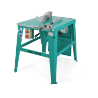
- The wedge and blade are aligned.
- The distance between the wedge and the blade is 3 to 8 mm
(Þ g. 10-A).
FIG.10-A
At the end of each work shift, remove the chips from the com-
partments protected by the lower and upper guards, so as to
keep the machine clean and in efÞ cient working order.
Regular maintenance of the machine helps to reduce the noise
levels to which the operator is exposed.
14. Major Servicing
The following more thorough checks should be made peri-
odically, at least every three months:
- that the machine does not show signs of slight damage which
could worsen dangerously over time;
- that the cutting disk stopping time is < 10 seconds, if not, do
not use the machine and make sure the belt is tensioned cor-
rectly (par. 11).
- that the cutting disc is fastened on its spindle;
- that the drive belts are properly tensioned and are not abnor-
mally worn.
15. Transport
The sawing machine can be moved while fully assembled, us-
ing various systems of lifting and transport.
If the machine has to be moved manually for short distances,
you are advised to buy the wheels and handle kit described in
point 16; alternatively, seek help from your colleagues.
If you wish to use a pallet, the machine must be fastened onto
it by means of ropes or nails in the holes in the support feet.
If lifting equipment is used, the sawing machine must be slung
by attaching the cables to the eyelets [10] (Þ g.1) at the four
corners of the machine.
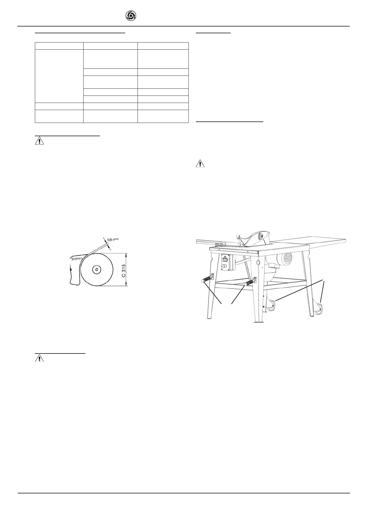
16. Wheels and handle kit
It is possible to procure an accessory wheels and handle kit, to
facilitate moving the machine.
The kit consists of a pair of handles [A1] (Þ g.11) and a pair of
wheels [B1], which must be bolted to the relevant Þ tting points
on the machine, as shown in Þ g. 11.
This kit can be used only within the building site, for moving
the machine occasionally and for short distances. The machine
must be moved by pulling and not pushing, as follows: 1) switch
off the machine and unplug it from the power supply; 2) turn
your back to the electrical panel and bend your knees so as to
grip the handles [A1] (Þ g.11) from behind; 3) straighten your
knees to lift the machine from the ground; 4) walk slowly for-
wards until you reach your intended location.
A1
B1
Fig. 11
 Loading...