26
IMER INTERNATIONAL S.p.A.
KOINE 3
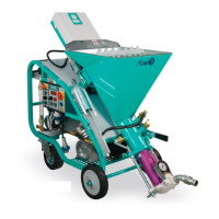
10.2 WATER CONNECTION
Connect the water hose (table 1) from the pump to the water mains.
The water mains must guarantee a minimum ow rate of
15l/min.
Otherwise a tank of suitable capacity (200 l) must be tted with
clean water, to be kept full at all times, and from which water can
be taken by means of the self-priming pump supplied with the
machine. In this case the hose must have a minimum diameter
of 3/4", a maximum length of 3m, preferably a foot lter and must
not be subject to deformation during use. Ensure that pressure is
sufcient. Turn the main switch to 1; the green light on the panel
illuminates (ref.8)
- CAUTION! The rst time the water pump is connected to
the tank, it must be activated by manually lling the intake line.
The same operation must be repeated each time the circuit
is drained, or after a prolonged period of disuse.
10.3 AIR CONNECTION
Connect the air hose to the machine panel and spray jet as shown
in the gure below.
Open the spray jet air valve.
FIG.7
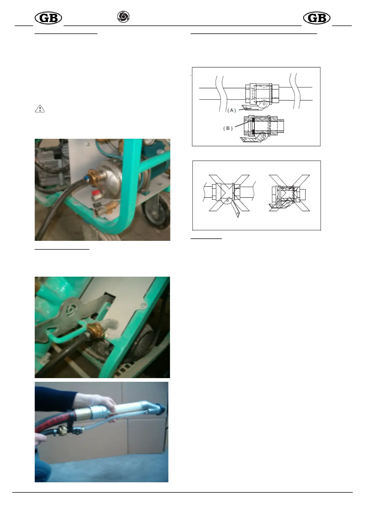
10.3 CORRECT CONNECTIONS FOR MATERIAL LINES
Take the material hoses and check that they are in perfect
condition, that the couplings are intact and all relative seals are
present. Check that the cam levers ( A ) of the couplings have
been tightened correctly and that the seal (B) is tted as shown
in the gure below.
( A )
( B )
11. START-UP
Before starting up the machine, check that the air valve on the
spray jet is open (ref.11).
Turn the main switch (ref.1) on the electrical panel to 1; the com-
pressor is activated. Using the two pushbuttons (ref.3), access
start command n°2(ref.4) on the display.
Remove the water level cap (ref.12), positioned a the side on
the lower section of the hopper unit and ensure that there is no
material obstructing the hole. If clogged, clean by means of the
longer section of the water level cap.
Press the water supplement button (ref.9) and check that the wa-
ter comes out of the relative hole of the water level cap. Use the
micrometric valve (ref.13) to set the water ow rate, as displayed
by the ow meter (ref.14) respectively
-at 300 l/min for cement-based products
-at 500 l/min for gypsum based products
Ret the water level cap in its hole and close securely.
Load the hopper with the relative premixed material in sacks.
Position the start selector (ref.5) to ON (rotate to the right), to
start up the machine.
Wait for material to be delivered from the jet and at the same time
load the material hopper.
At this point the mix delivered by the jet can be adjusted by cor-
recting the quantity of water as required.
Use the micrometric valve, reducing the ow rate by 20l at a time,
to obtain the required consistency.
When the jet starts to deliver material at the required consistency,
normal work can be started.
The machine starts and stops by opening and closing the air
supply to the spray jet.
The machine is tted with protection against power failure or surges
(see paragraph Errors, page 8): if one of these events occurs, the
thermal cut-out trips. In this case reset the switch (ref.5) and turn
the main switch to 1.
In the event of water pressure failure (see tableTroubleshooting,
page 10), the motor shuts down and the green light turns off (ref.8).
The machine restarts automatically when sufcient pressure is
restored.
To stop the machine in the event of an emergency, press the red
emergency button (ref.10) - all moving parts are shut down - then
turn the main switch to 0 and remove the electric power plug from
the mains socket.