IMER U.S.A. Inc.
8
MINUTEMAN
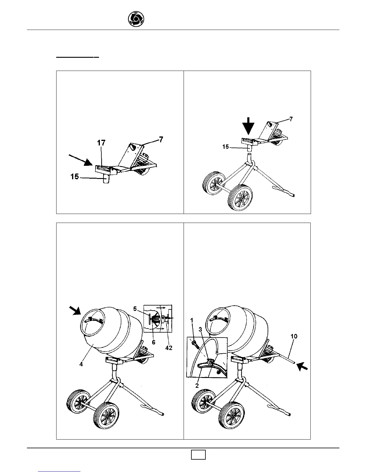
Fit the gear-box frame and motor assembly
(# 7 Drawing 1) into the swivel bracket (# 15
Drawing 1) with the anchor pin, (# 17 Drawing
1) slide the cotter pin through the anchor pin
hole (# 16 Drawing 1).
3
4
56
Mount the mixing drum (# 4 Drawing 1) onto
the gear-box shaft (# 42 - # 6 Drawing 2) by
aligning the guide notch with the locating pin
on the gear shaft.Secure the drum to the gear-
box shaft with the T-handle bolt(# 5 Drawing 1)
and washer (# 6 Drawing 1) provided in the
assembly kit.
ASSEMBLY
Secure the mixing blades (# 2 Drawing 1) to
the inner drum with the screws (# 1 Drawing
1) and nuts (# 3 Drawing 1) provided in the
assembly kit.Assembly with the screws heads
on the outer drum.
Finally, insert tilting handle (# 10 Drawing 1)
in the handle mounting tube and lock using the
cotter pin provided in the assembly kit.
Slide the swivel bracket (# 15 Drawing 1) onto
the main frame upright. The gear-box and
motor assembly (# 7 Drawing 1) is mounted
into this swivel bracket.


 To Next Page