EasyManua.ls Logo

IMG STAGELINE PMX-400 - User Manual

IMG STAGELINE PMX-400
26 pages
Print Icon
To Next Page IconTo Next Page
Loading...
5
LO
+15–15 dB
0
HI
+15–15 dB
0
LO
+15–15 dB
0
HI
+15–15 dB
0
LO
+15–15 dB
0
HI
+15–15 dB
0
LO
+15–15 dB
0
HI
+15–15 dB
0
GAIN
LO
HI
GAIN
LO
HI
GAIN
LO
HI
GAIN
LO
HI
LEFT
(MONO)
RIGHT
5-6
LEFT
(MONO)
RIGHT
LEFT
(MONO)
RIGHT
LEFT
(MONO)
RIGHT
7-8 9-10 11-12
L
L
R
R
FX
MON
LEFT
(MONO)
RIGHT
AUX
INPUT
OUTPUT
100 100
100
5
5
AUX
IN
FX
OUT
MON
OUT
100
PHONES
5
THERMAL
PLAY
L
L
R
R
TAPE
TAPE
48V
PHANTOM
POWER
100
5
POWER
ON
L CLIP
R CLIP
LEVEL
REC
LOUDNESS
AMPLIFIER STATUS
600W
ON
OFF
RIGHTLEFT
+18
+15
+12
+9
+6
+3
0dBu
-3
-6
-9
-12
-18
+10 +50
+15
350 6k
RL
100
GAIN
HI
MID
LO
FX
MON
PAN
INST VOC
PEAK
PFL
MIC
LINE
1
1
C
5
0
Hz
–15 dB
+15–15 dB
0
+15–15 dB
0
100
5
+10 +50
+15
350 6k
RL
100
GAIN
HI
MID
LO
FX
MON
PAN
INST VOC
PEAK
PFL
MIC
LINE
2
2
C
5
0
Hz
–15 dB
+15–15 dB
0
+15–15 dB
0
100
5
+10 +50
+15
350 6k
RL
100
GAIN
HI
MID
LO
FX
MON
PAN
INST VOC
PEAK
PFL
MIC
LINE
3
3
C
5
0
Hz
–15 dB
+15–15 dB
0
+15–15 dB
0
100
5
+10 +50
+15
350 6k
RL
100
GAIN
HI
MID
LO
FX
MON
PAN
INST VOC
PEAK
PFL
MIC
LINE
4
4
C
5
0
Hz
–15 dB
+15–15 dB
0
+15–15 dB
0
100
5
RL
100
FX
MON
BAL
PEAK
PFL
5-6
C
5
100
5
RL
100
FX
MON
BAL
PEAK
PFL
7-8
C
5
100
5
RL
100
FX
MON
BAL
PEAK
PFL
9-10
C
5
100
5
RL
100
FX
MON
BAL
PEAK
PFL
11-12
C
5
100
5
PMX-400
600W POWERED MIXER
LEFT
(MONO)
RIGHT
5-6
LEFT
(MONO)
RIGHT
LEFT
(MONO)
RIGHT
LEFT
(MONO)
RIGHT
7-8 9-10 11-12
L
L
R
R
MAIN OUT
MIC
LINE
1
MIC
LINE
2
MIC
LINE
3
MIC
LINE
4
MAIN/PFL
OFF
ON
INSERT
(TIP: SEND RING: RETURN)
STEREO POWER MIXER
TABLE DE MIXAGE AMPLIFIÉE STÉRÉO
MIXER STEREO DI POTENZA
PMX-400 Best.-Nr. 20.1630
BEDIENUNGSANLEITUNG • INSTRUCTION MANUAL • MODE D’EMPLOI
ISTRUZIONI PER L’USO • GEBRUIKSAANWIJZING • HANDLEIDING
CONSEJOS DE SEGURIDAD • SIKKERHEDSOPLYSNINGER • SÄKERHETSFÖRESKRIFTER • TURVALLISUUDESTA
Question and Answer IconNeed help?

Do you have a question about the IMG STAGELINE PMX-400 and is the answer not in the manual?

Summary

1 Operating Elements and Connections

1.1 Front Panel

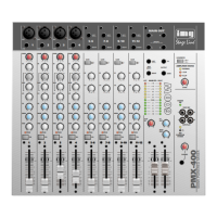
Detailed explanation of controls and inputs on the mixer's front panel, including channel strips and master section.

1.2 Rear Panel

Description of connections and controls located on the mixer's rear panel, such as mains input and speaker outputs.

2 Safety Notes

3 Applications

4 Setting-up and Rack Installation

5 Connections

5.1 Input Channels

Instructions on how to connect various audio sources like microphones and line-level instruments to the mixer's input channels.

5.2 Inserting Effect Units

Guidance on connecting external effects processors using either the dedicated FX send/return or the insert jacks for signal modification.

5.3 Connecting Headphones and Monitoring System

How to connect headphones for monitoring and setting up a stage monitoring system via the dedicated monitor output.

5.4 Connecting a Sound Recorder

How to connect audio recording equipment to the mixer's tape inputs and outputs for recording and playback.

5.5 Master Output

Details on connecting the main stereo output (MAIN OUT) to amplifiers, external mixers, or other audio equipment.

5.6 Connecting Speakers

Information on connecting loudspeakers to the mixer's amplifier outputs, including impedance considerations and cable types.

5.7 Power Supply

Instructions for connecting the mixer to the mains power supply using the provided cable and socket.

6 Operation

6.1 Basic Input Channel Setup

Initial steps for setting up input channels, including adjusting gain, EQ, pan, and fader levels before mixing.

6.2 Mixing Audio Sources

Procedures for balancing and adjusting levels of different audio sources to create the final mix using channel faders and master controls.

6.3 Monitoring via Headphones

How to listen to the master or prefader signals using headphones and adjust the volume for comfortable monitoring.

6.4 Warning Indications of the Power Amplifier

Explanation of the indicator lights (CLIP, THERMAL) that signal potential issues with the power amplifier, such as overload or overheating.

7 Modifications

7.1 Modifying Send Ways

Procedures for changing internal jumpers (JP1, JP2) to alter signal routing for effect and monitor sends (post/pre fader).

7.2 Switching Off Phantom Power for Individual Channels

Instructions on how to disconnect the 48V phantom power for specific mono channels by cutting a link (LK1).

8 Specifications

IMG STAGELINE PMX-400 Specifications

General IconGeneral
BrandIMG STAGELINE
ModelPMX-400
CategoryMixer
LanguageEnglish