PPI-2 REV. J IMPCO Technologies Inc November, 2014
3030 South Susan St. Page 10 of 16
Santa Ana, CA 92704
www.impcotechnologies.com
3030 S Susan Street, Santa Ana, CA 92704
Ph: +1 714 656 1200 Fax: +1 714 656 1400
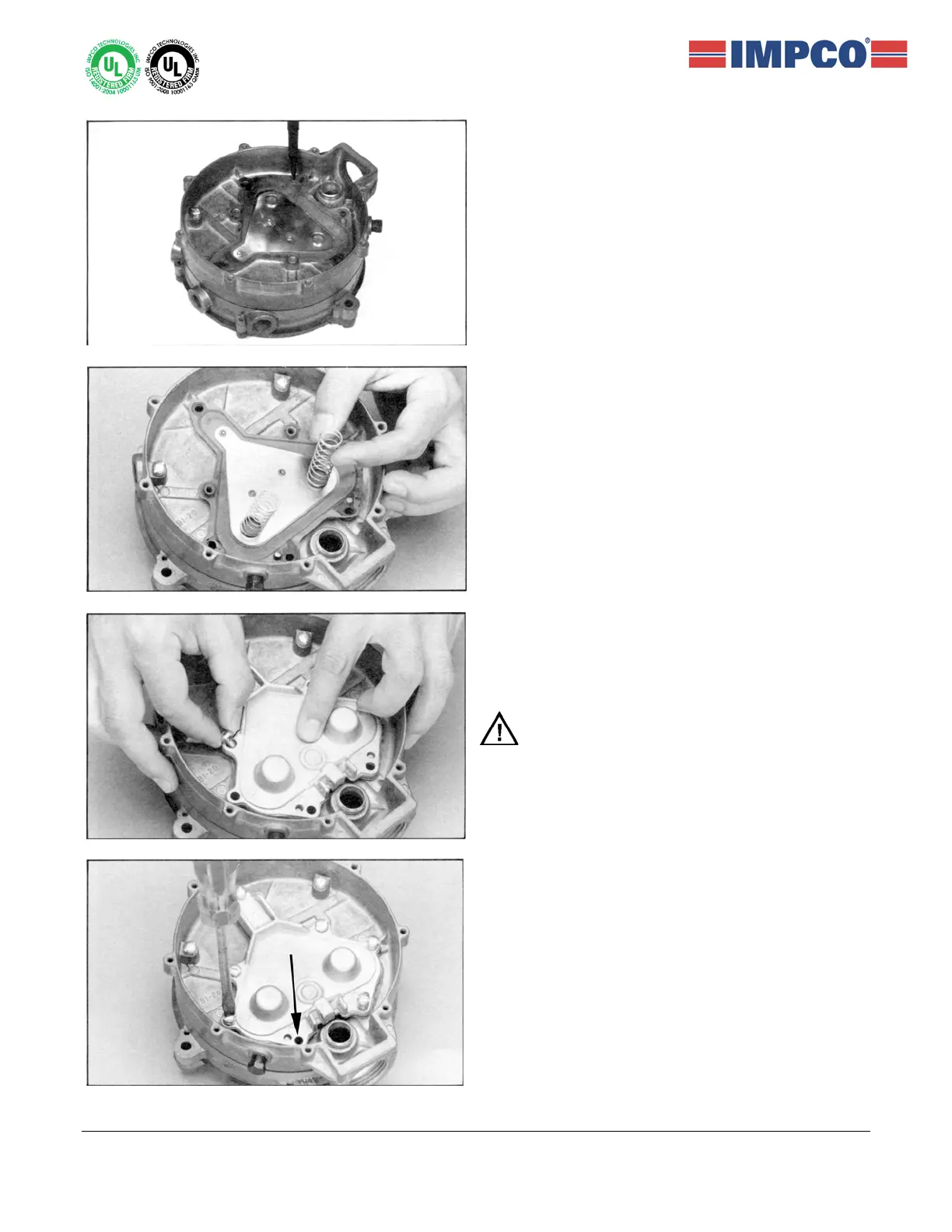
26. Install the primary diaphragm (13) over the
locating pins and screw bosses, providing
alignment for the assembly of the springs (12)
and cover (11).
27. Place the two primary valve springs (12) on their
locating perches extruded from the backup plate
on the primary diaphragm (13).
28. Press the primary cover (11) in place over the
primary valve springs (12) and diaphragm
assembly (13). Insert two screws (9) and finger
tighten.
Note that two screws (9) securing the top of
primary cover (11) and in the center are different
from the other four screws (10).
29. Early Models: Replace four of the five screws
(10). DO NOT replace the one shown by the
arrow. Torque to 35-45 in-lbs. (4.0-5.1 Nm).
Torque the two inner screws (9) to 22-28 in-lbs.
(2.5-3.2 Nm).
Later Models: Replace all five screws (10) and
torque to 35-45 in-lbs. (4.0-5.1 Nm). Torque the
two inner screws (9) to 22-28 in-lbs. (2.5-3.2
Skip to Step 35.
 Loading...