PPI-2 REV. J IMPCO Technologies Inc November, 2014
3030 South Susan St. Page 8 of 16
Santa Ana, CA 92704
www.impcotechnologies.com
3030 S Susan Street, Santa Ana, CA 92704
Ph: +1 714 656 1200 Fax: +1 714 656 1400
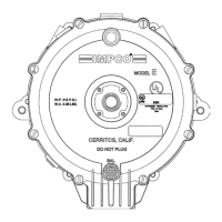
19. Deposits may accumulate from the use of hard
water. This condition can be alleviated through
the use of radiator additives or permanent
antifreeze solutions. Remove any accumulation
with a wire brush before assembly. Steel water
inlet and outlet fittings may cause erosion from
electrolysis. Use brass or plastic water fittings
only.
REASSEMBLY OF REGULATOR
• Carefully clean and inspect all metal parts; springs, levers, pivot pins and screws. Replace all parts
that are included in the repair kits.
• Carefully clean the body casting and inspect all sealing surfaces . Wipe with a clean rag. Inspect
the primary section for foreign materials that might loosen and damage the soft face valves.
• Clear out the inlet and outlet passages with compressed air. Be sure no foreign material remains in
these passages.
• Inspect the primary orifice and the secondary orifice for nicks, scratches or uneven wear.
IMPORTANT!
If the primary or secondary seats show any of the above mentioned conditions, the regulator is not
rebuildable and must be replaced.
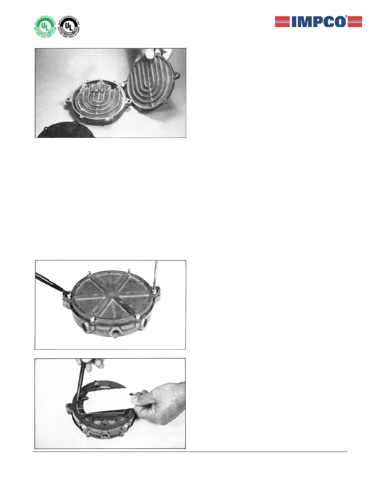
20. Reassemble the back cover (22) and gasket (21)
to the heat exchanger body (19). Replace six
screws (2). Match the mounting bosses in the
cover with those on the heat exchanger. Tighten
the two screws shown in the photo first, then
upper and lower screws diagonally opposite to
draw the cover down evenly. Torque to 25-35 in-
lbs (2.8-4.0 Nm).
21. The pen indicates the recess cast in the body
(19) to retain the sponge (17). Be sure to
accurately install the sponge in the recess.
 Loading...