Do you have a question about the Impex MARCY PLATINUM MP-3105 and is the answer not in the manual?
Essential safety measures and precautions to follow when operating exercise equipment.
Guidelines for lubricating, inspecting, cleaning, and weight limits for the exercise machine.
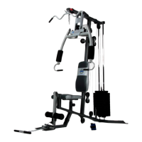
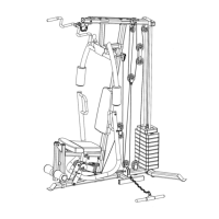
Initial assembly steps involving diagonal supports, cross braces, and rear vertical beam connections.
Attaching the left vertical beam, guide rod, safety stop frame, and guide rod bracket.
Connecting weight glide posts, upper frame, and frame supports to the main structure.
Attaching butterfly base, pulley bracket, arm pads, and backrest board to the frame.
Routing and connecting cables, pulleys, and the lat bar for the weight system.
Connecting butterfly cables to pulleys and brackets for proper operation.
Connecting cables to rear vertical beam, weight glide post base, and floating pulley brackets.
Installing weight lifting sleeve, Olympic sleeves, spring clips, bar holders, and safety catches.
Attaching main seat support, front post, and securing with lock pins.
Attaching seat bracket, backrest supports, incline support, and foam tube assembly.
Attaching the seat pad and bench backrest board to the assembled seat bracket.
Instructions and information required for ordering replacement parts for the exercise machine.
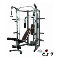
| Type | Home Gym |
|---|---|
| Brand | Impex |
| Model | MARcy Platinum MP-3105 |
| Weight Capacity | 300 lbs |
| Material | Steel |
| Color | Black |
| Warranty | 2 years |