EasyManua.ls Logo

Inbay 241170-53-1 User Manual

Inbay 241170-53-1
20 pages
To Next Page IconTo Next Page
Page #1 background imageLoading...
Page #1 background image
1
© 2018 · acv GmbH · Straßburger Allee 10-12 · 41812 Erkelenz www.inbay.systems
level of difcultySchwierigkeitsgrad
An appropriate installation in observance of these operating instructions
is necessary. Please make sure the wiring is arranged so it is not bended
or crimped due to the risk of cable break. Make sure that all connections
are correct. Route the cable away from moving parts, do not allow the
cable to be entangled, pinched or damaged in any way.
We will not be liable for damage due to improper installation or utilization.
Use the specied accessory parts to prevent product failure.
Subject to technical modifications; no responsibility is accepted for the
accuracy of this information.
The “Qi” symbol is a trademark of the “Wireless Power Consortium”
EINBAUANLEITUNG
D
INSTALLATION GUIDE
GB
gering hoch low high
www.inbay.systems
2021-07-26
Sachgemäße Installation unter Beachtung dieser Einbauanleitung erfor-
derlich. Achten Sie auf korrekte Anschlüsse. Verlegen Sie die Kabel so, dass
Sie weder geknickt, gequetscht oder beschädigt werden können. Sorgen
Sie dafür, dass sich die Kabel nicht in Gegenständen verfangen können.
Wir können keine Haftung für Schäden übernehmen, welche durch un-
sachgemäße Installation oder Nutzung verursacht wurden. Verwenden Sie
darum ausschließlich das mitgelieferte Montagematerial.
Technische Änderungen vorbehalten, alle Angaben ohne Gewähr.
Das „Qi“ Logo ist Warenzeichen des „Wireless Power Consortium“
Wireless Charging Tray
Mazda CX-5 (KF) 05/2017>
241170-53-1
A
B
Beispielillustration / sample illustration
Question and Answer IconNeed help?

Do you have a question about the Inbay 241170-53-1 and is the answer not in the manual?

Inbay 241170-53-1 Specifications

General IconGeneral
BrandInbay
Model241170-53-1
CategoryAutomobile Battery Charger
LanguageEnglish

Summary

Wireless Charging Tray Installation Guide

Installation Difficulty and Overview

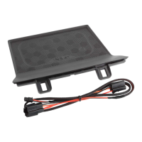
Details the installation complexity and provides an overview of the wireless charging tray setup.

General Installation Safety and Guidelines

Provides crucial advice on correct wiring, cable routing, liability, and technical modifications.

Vehicle Preparation and Console Disassembly

Model Compatibility: Automatic Transmission

Specifies that these instructions are for automatic transmission vehicles; manual models require different steps.

Gear Lever Release Procedure

Demonstrates the procedure to release the gear lever for accessing the center console components.

Console Trim Panel Removal Steps

Illustrates the process of carefully removing trim panels around the gear shift area for access.

Accessing Vehicle Electrical Connectors

Shows specific electrical connectors on the vehicle's control unit to be accessed for wiring.

Wiring Integration and Harness Connection

Console Cable Routing and Management

Details the correct routing of cables through the console to avoid damage or entanglement.

Connecting the Main Charging Harness

Illustrates the direct connection of the charging harness to the vehicle's wiring loom.

Final Harness and Component Connections

Details the final connection of the charging system's wiring harness components and small plugs.

Charging Tray Installation and Functional Testing

Installing the Wireless Charging Tray Unit

Demonstrates placing and securing the wireless charging tray into its designated position.

Securing the Tray Unit in Place

Illustrates the final steps of pushing the charging tray into place until it clicks, securing it.

Verifying Wireless Charging Functionality

Shows a smartphone placed on the tray, indicating successful wireless charging initiation.

Important Usage Warnings and Post-Installation Tasks

Prohibited Items on Charging Tray

Warns against placing metal objects, credit cards, or phones with ring holders on the charging surface.

Surface Temperature and Power Warnings

Alerts users to potential heat generation and the +12V socket power limit (5A/60W).

Manual Placement in Glove Box

Instructs to place the installation manual in the customer's glove box after the installation is complete.