Do you have a question about the inbody 370 and is the answer not in the manual?
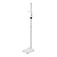
Remove packing materials, raise the stand, and tighten the joint screw.
Adjust leveling screws for accuracy and plug in the power adapter.
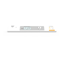
Turn on the InBody370 and allow it to initialize for 15 seconds.
Begin weight measurement and remain still for accurate results.
Enter and confirm personal details like ID, height, age, and gender.
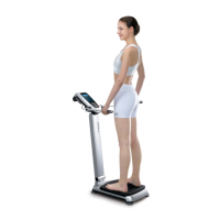
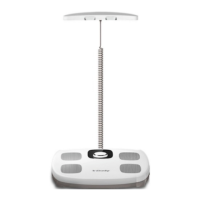
Maintain proper posture, arm position, and electrode grip during the test.
Avoid static electricity, carpets, and liquids; use InBody tissue for cleaning.
Do not dismantle the device or use with other electronic medical equipment.
Address common error messages by restarting or checking subject data/contact.
Calibrate the touchscreen via SETUP or restart for responsiveness issues.
Check impedance values on the results sheet for proper downward trend.
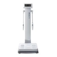
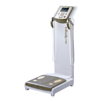
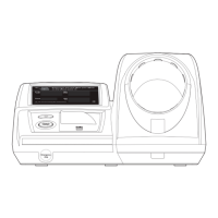
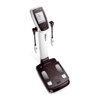
The InBody370 is a body composition analyzer designed for healthy life and InBody tests. It provides detailed body composition analysis, including weight, skeletal muscle mass, body fat mass, and obesity analysis, along with BMR and BMI.
The InBody370 measures body composition by utilizing bioelectrical impedance analysis (BIA). Users stand on the footplate electrodes and grip the hand electrodes, allowing a small, safe electrical current to pass through the body. The device then calculates various body composition parameters based on the impedance measured at different frequencies (5 kHz, 50 kHz, 250 kHz) for different body segments (Right Arm, Left Arm, Trunk, Right Leg, Left Leg). The results are displayed on a touchscreen and can be printed on a result sheet. The device is designed to provide reliable and reproducible results, emphasizing proper posture during the measurement process.
| Brand | inbody |
|---|---|
| Model | 370 |
| Category | Measuring Instruments |
| Language | English |