PREFACE Page P-3
P
LS300 User’s Guide
Each product line must be precision tested and verified free of leaks before any component of the
LS300 system is installed. After verification, the LS300 Auto-Learn
®
system is installed, wired, and
calibrated. The supplied leak-generating device/calibration kit* is attached to a needle valve, and the
appropriate line channel selector switch is placed in the learn position at the console. Each line is
calibrated separately, one at a time, to “learn” the parameters and characteristics of a line with a
known induced leak-rate.
At each STP housing, the needle valve kits* are assembled and installed in the pressure test ports,
and the LSU300 pressure-transducers are installed in 2 inch NPT line leak detector ports (LSU300
cable length must not exceed 500 feet).
After a line is calibrated the leak-generator device is moved to the next product line for Auto-Learn
calibration. The entire process is repeated until all lines are separately calibrated and the console is
left in the Run – Detect mode.
The front panel has a power on light and 4 status-lights per line. The status lights show currently
running line leak tests, faults, and alarms. Fault-alarms will cause indicator lights to blink or flash.
Certain alarms will also activate the internal alarm horn. Manual line leak tests may be started and
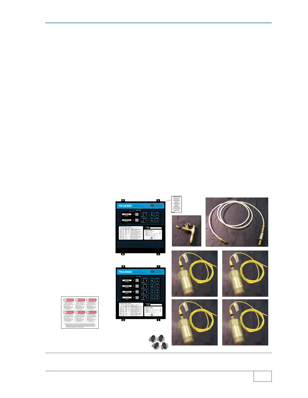
Figure P-1 LS300 LLD System Components
2 CHNL LS300
* The needle valve kit and the leak generating device/calibration kit have not been
evaluated by Underwriters Laboratories
.
LEAK GENERATING
DEVICE
NEEDLE
VALVE
LSU300 TRANSDUCER
# 3 with
3/4 Chnl
# 4 with
4 Chnl
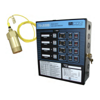
PRODUCT
ID
STICK-ON
DANGER
3 OR 4 CHNL
NO-STRIP
SPLICE
2 CHNL
 Loading...