©2016 by Taylor Design Group, Inc. All rights reserved. Rev.6/16
Page 8
Manufactured by Taylor Design Group, Inc. P.O. BOX 810262 Dallas, TX 75381 WWW.INCRA.COM
MADE IN THE
USA
Taylor Design Group, Inc. P. O. B OX 81 0 26 2 D al l a s, T X 75 3 81 P: 97 2- 24 2- 9 9 75 F: 97 2- 24 2- 9 98 5 www.incra.com
INCRA is a Registered Trademark of Taylor Design Group, Inc. ©2016 Taylor Design Group, Inc.
INCRA MITER5000 OWNER’S MANUAL
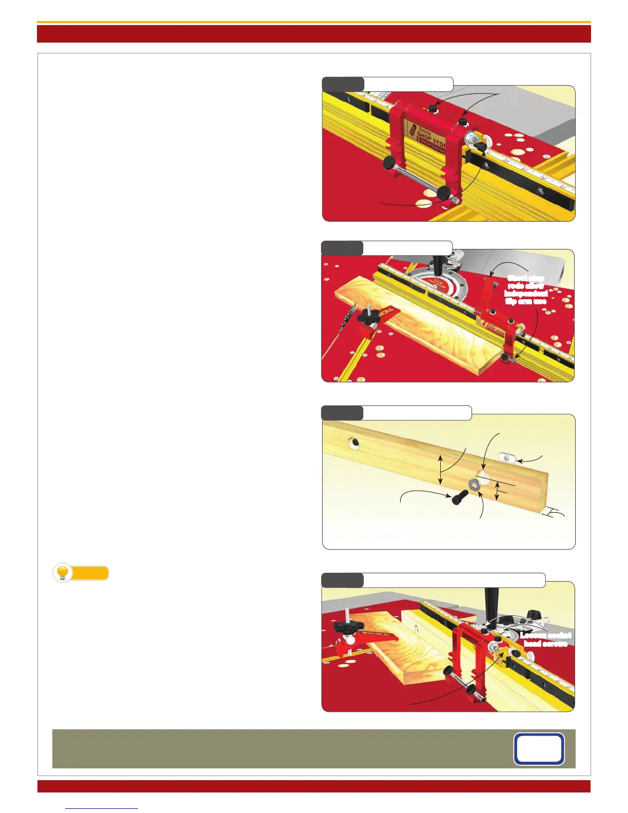
Fig. 27
Micro Adjusting
Fig. 29
Making a Sub-Fence
Loosen (2)
socket head screws
Turn this socket
head screw to
adjust
2-1/2” max
(see note)
Fig. 30
Expanded Flip Stop Clamping Mode
Slide red assembly
into 2nd T-slot on gold
component
1/4-20
rectangular nut
Loosen socket
head screws
Fig. 28
Short Stop Rods
Short stop
rods allow
independent
ip arm use
Micro Adjusting
To micro adjust your Flip Shop Stop’s position, begin by
loosening the (2) socket head screws located on the top
of the stop body. Now turn the micro adjust socket head
screw to ne tune the stop position, Fig. 27. When un-
screwing the micro adjust screw, apply pressure to the stop
body to keep it against the screw end. After adjustment,
always tighten the (2) socket head screws on top of the
stop body.
Flip Arms and Stop Rods
The dual ip arms and stop rods provide a variety of stop
congurations. The ip arms can be used without the stop
rods when you want to take advantage of the fence/arm
tongue and groove feature for stop control on mitered
board ends. Typically, you will use the longer rod to join
the two arms together. This produces an arrangement
that, when pivoted, moves both arms simultaneously. The
rod can be positioned so that it is the actual stop surface
or it can be positioned slightly behind the front of the arm
so that the aluminum arm is the actual stop surface.
By placing one of the shorter 1-1/2” rods in each of the two
stop arms, you can use the two stop arms independently,
Fig. 28. For example, you can calibrate one for work to
the left of the blade and the other for work to the right.
On one side of the blade you might want to position the
stop rods to provide two different cut off lengths from one
stop position. By using varying combinations of long or
short rods you can create as much as 7-3/4” between the
two stop positions.
Making a Zero Clearance Wooden Sub-Fence
A sub-fence can be used to provide tear out control as well
as support for your workpiece up to and beyond the blade.
A good material to use for making your zero clearance sub-
fence is 3/4” medium density berboard (MDF). Use the
drill and counter bore dimensions shown in Fig. 29. Attach
using the supplied fasteners. Adjust the length of the fence
to accommodate your application. Note: In applications
where the incremental stopping capability of the Flip Shop
Stop is required, the wooden sub-fence can be no taller
than 2-1/2”.
To avoid the saw blade pulling your work-
piece into the cut, add a strip of adhesive
backed sandpaper to the front face of the wooden sub-
fence.
Expanded Flip Stop Clamping Mode
The two-part body design of the INCRA Flip Shop Stop al-
lows for use with up to a 3/4” thick wooden sub-fence. To
expand the INCRA Flip Shop Stop, loosen the (2) socket
head screws located on the top of the stop body, then slide
the upper portion of the stop off. Now slide the upper
portion back on, capturing the rectangular nuts in the sec-
ond T-slot located on the lower portion (gold component)
of the stop body, Fig. 30.
TIP
1/4-20x3/4” socket head
screw
1/4 at washer
1-1/16”
3/4”
5/16” through hole w/ 3/4”
dia. x 3/8” deep counter bore
 Loading...